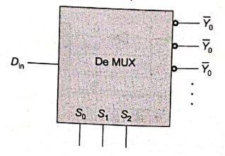
A 1-to-8 demultiplexer with data input D∈ , address inputs S0,S1,S2 (with S0 as the LSB) and Yˉ0toYˉ7 as the eight demultiplexed outputs, is to be designed using two 2-to-4 decoders (with enable E input and address inputs A0andA1 ) as shown in the figure. D∈,S0,S1andS2 are to be connected to P, Q, R and S, but not necessarily in this order. The respective input connections to P, Q, R, and S terminals should be