GATE CE · Structural Analysis
Generate GATE-level questions on Influence Line Diagram And Rolling Loads in Structural Analysis. Focus on core concepts, previous year patterns, and numerical problem-solving techniques.
17 questions · 17 PYQs · 0 AI practice · GATE CE 2027
🎯 These are sample questions
Just sign in to unlock everything. Free for all students.
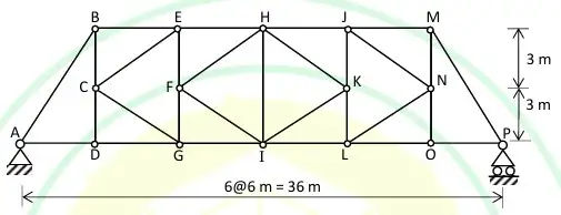
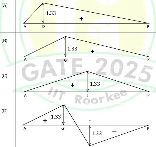
Consider the pin-jointed truss shown in the figure. Influence line is drawn for the axial force in the member G-L when a unit load travels on the bottom chord of the truss. Identify the CORRECT influence line from the following options: Note: Positive value corresponds to tension and negative value corresponds to compression in the member.


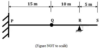
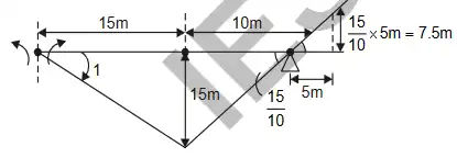
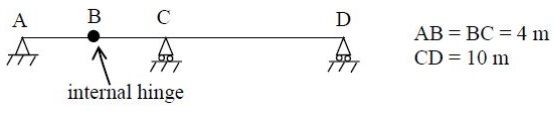
The horizontal beam shown in the figure has a fixed support at point , an internal hinge at point , and a pin support at point . A concentrated vertically downward load of can act at any point over the entire length of the beam. The maximum magnitude of the moment reaction (in ) that can act at the support due to is ______ (in integer).

Muller-Breslau principle is used in analysis of structures for
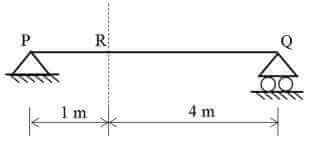
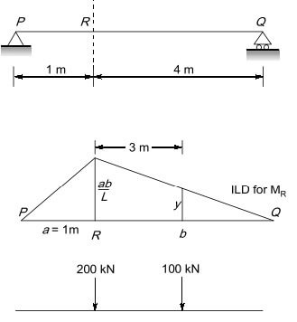
Consider a simply supported beam PQ as shown in the figure. A truck having 100 kN on the front axle and 200 kN on the rear axle, moves from left to right. The spacing between the axles is 3 m. The maximum bending moment at point R is ______ kNm. (in integer)

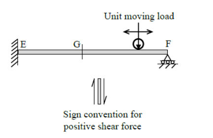
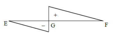
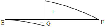
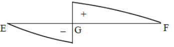
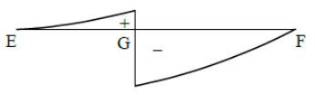
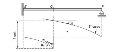
A propped cantilever beam EF is subjected to a unit moving load as shown in the figure (not to scale). The sign convention for positive shear force at the left and right sides of any section is also shown. The CORRECT qualitative nature of the influence line diagram for shear force at G is


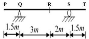
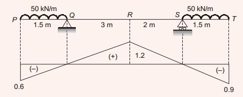
Distributed load(s) of 50 kN/m may occupy any position(s) (either continuously or in patches) on the girder PQRST as shown in the figure The maximum negative (hogging) bending moment (in kNm) that occurs at point R, is

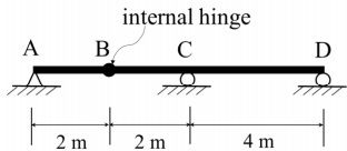
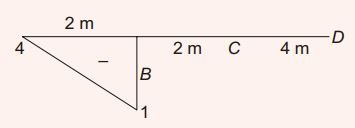
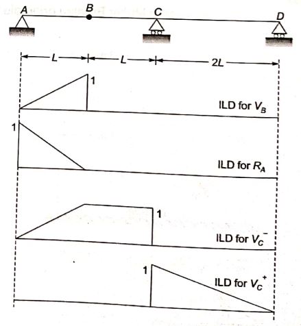
A long uniformly distributed load of 10 kN/m and a concentrated load of 60 kN are moving together on the beam ABCD shown in the figure. The relative positions of the two loads are not fixed. The maximum shear force (in kN, round off to the nearest integer) caused at the internal hinge B due to the two loads is _____

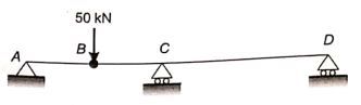
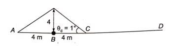
Consider the beam ABCD shown in the figure. For a moving concentrated load of 50 kN on the beam, the magnitude of the maximum bending moment (in kN-m) obtained at the support C will be equal to _____

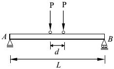
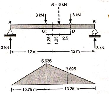
A simply supported beam AB of span, L=24 m is subjected to two wheel loads acting at a distance, d=5m apart as shown in the figure below. Each wheel transmits a load, P=3 kN and may occupy any position along the beam. If the beam is an I-section having section modulus, S=16.2 , the maximum bending stress (in GPa) due to the wheel loads is ___________.

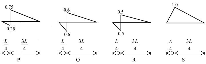
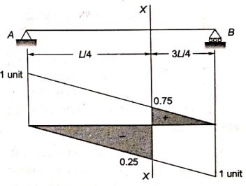
In a beam of length L, four possible influence line diagrams for shear force at a section located at a distance of from the left end support (marked as P, Q, R and S) are shown below. The correct influence line diagram is

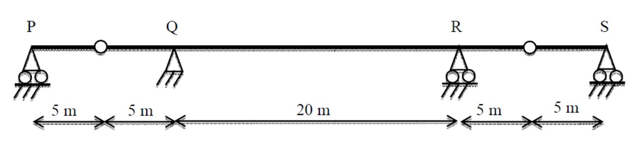
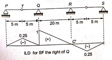
Beam PQRS has internal hinges in spans PQ and RS as shown. The beammay be subjected to a moving distributed vertical load of maximum intensity 4 kN/m of any length anywhere on the beam. The maximum absoulate value of the shear force that can occur due to this loading just to the right of support Q shall be:

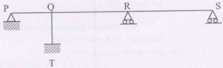
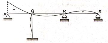
The span(s) to be loaded uniformly for maximum positive (upward) reaction at support P, as shown in the figure below, is (are)

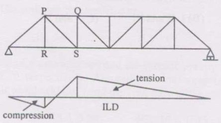
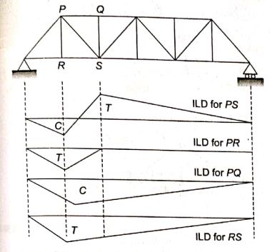
The influence line diagram (ILD) shown is for the member

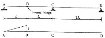
Consider the beam ABCD and the influence line as shown below. The influence line pertains to

A beam PQRS is 18 m long and is simply supported at points Q and R, 10 m apart. Overhangs PQ and RS are 3 m and 5 m respectively. A train of two point loads of 150 kN and 100kN, 5 m apart, crosses this beam from left to right with 100 kN load leading. The maximum hogging moment in the beam anywhere is
Muller Breslau's principle in structural analysis is used for
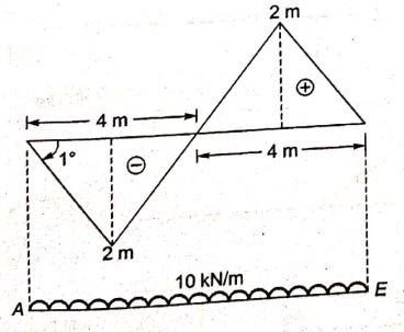
Identify, from the following, the correct value of the bending moment (in kNm units) at the fixed end A in the statically determinate beam shown below (with internal hinges at B and D), when a uniformly distributed load of 10 kN/m is placed on all spans. (Hint: Sketching the influence line for or applying the Principle of Virtual Displacements makes the solution easy).

Want unlimited AI-generated Influence Line Diagram And Rolling Loads questions?
Sign up free and practice with adaptive difficulty — Easy, Medium, Hard. New questions every session.
Start practising for free →