GATE EE · Electric Circuits
Generate GATE-level questions on Two-port networks. Focus on: 1. Impedance (Z), Admittance (Y), Hybrid (h), and Transmission (ABCD) parameters. 2. Interconnection of two-port networks (series, parallel, cascade). 3. Network functions: Driving point and Transfer functions, Poles and Zeros.
17 questions · 17 PYQs · 0 AI practice · GATE EE 2027
🎯 These are sample questions
Just sign in to unlock everything. Free for all students.
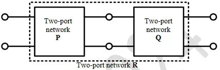
Two passive two-port network and are connected as shown in the figure. The impedance matrix of network is
. The admittance matrix of network is
. Let the matrix of the two-port network in the figure be
. The value of in is _______ (rounded off to 2 decimal places)

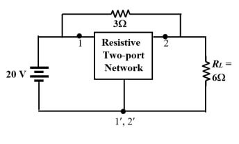
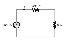
The admittance parameters of the passive resistive two-port network shown in the figure are The power delivered to the load resistor in Watt is ____ (Round off to 2 decimal places).

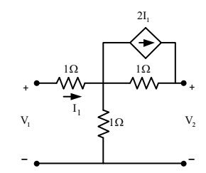
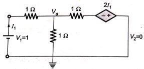
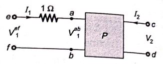
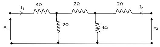
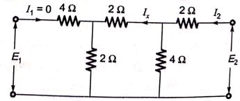
In the two-port network shown, the parameter (where, , when =0) in ohms is _____________ (up to 2 decimal places).

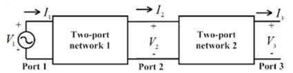
Two passive two-port networks are connected in cascade as shown in figure. A voltage source is connected at port 1. Given are the generalized circuit constants. If the Thevenin equivalent circuit at port 3 consists of a voltage source and impedance connected in series, then
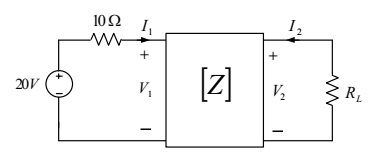
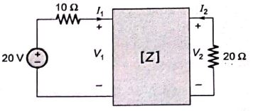
The z-parameters of the two port network shown in the figure are and . The average power delivered to , in watts, is _______.

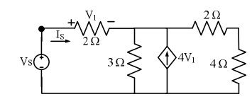
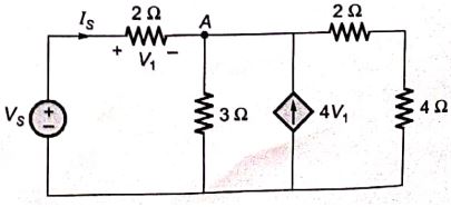
The driving point input impedance seen from the source of the circuit shown below, in , is ______.

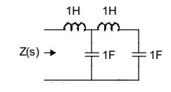
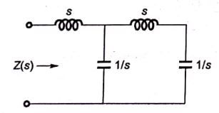
The driving point impedance Z(s) for the circuit shown below is

With 10 V dc connected at port A in the linear nonreciprocal two-port network shown below, the following were observed: (i) 1 connected at port B draws a current of 3 A (ii) 2.5 connected at port B draws a current of 2 A For the same network, with 6 V dc connected at port A, 1 connected at port B draws 7/3 A. If 8 V dc is connected to port A, the open circuit voltage at port B is

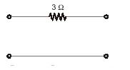
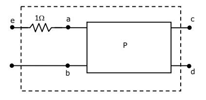
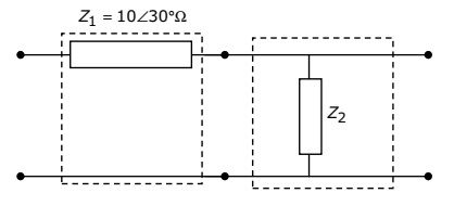
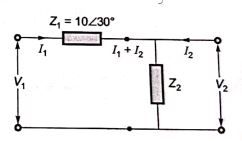
The two-port network P shown in the figure has ports 1 and 2, denoted by terminals (a,b) and (c,d) respectively. It has an impedance matrix Z with parameters denoted by . A 1 resistor is connected in series with the network at port 1 as shown in the figure. The impedance matrix of the modified two-port network (shown as a dashed box ) is

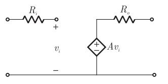
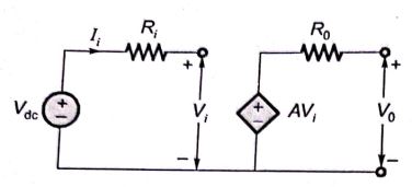
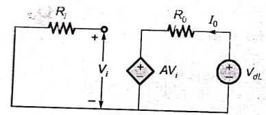
The parameter type and the matrix representation of the relevant two port parameters that describe the circuit shown are

The parameters of the circuit shown in the figure are . If , then output voltage, input impedance and output impedance respectively are

Two networks are connected in cascade as shown in the figure. With usual notations the equivalent A,B,C and D constants are obtained. Given that, C = 0.025 , the value of is

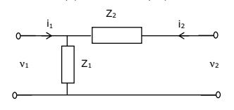
For the two port network shown in the figure, the Z-matrix is given by

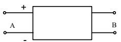
The Z-matrix of a 2-port network as given by
The element of the corresponding Y-matrix of the same network is given by
The h-parameters for a two-port network are defined by
. For the two-port network shown in figure, the value of is given by

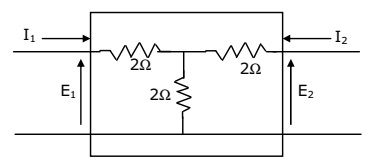
A two port network, shown in figure is described by the following equations The admittance parameters for the network shown are

A passive 2-port network is in a steady-state. Compared to its input, the steady state output can never offer
Want unlimited AI-generated Two Port Network And Network Functions questions?
Sign up free and practice with adaptive difficulty — Easy, Medium, Hard. New questions every session.
Start practising for free →