Q1GATE 2018MCQ
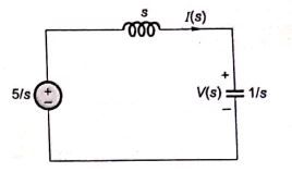
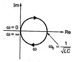
A DC voltage source is connected to a series L-C circuit by turning on the switch S at time t=0 as shown in the figure. Assume i(0)=0, v(0)=0. Which one of the following circular loci represents the plot of i(t) versus v(t) ?


GATE EE · Electric Circuits
Generate GATE-level questions on Resonance. Focus on: 1. Series and Parallel Resonance. 2. Quality factor (Q), Bandwidth, and selectivity. 3. Locus diagrams for RL and RC circuits.
16 questions · 16 PYQs · 0 AI practice · GATE EE 2027
🎯 These are sample questions
Just sign in to unlock everything. Free for all students.
A DC voltage source is connected to a series L-C circuit by turning on the switch S at time t=0 as shown in the figure. Assume i(0)=0, v(0)=0. Which one of the following circular loci represents the plot of i(t) versus v(t) ?
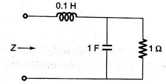
The voltage v(t) across the terminals a and b as shown in the figure, is a sinusoidal voltage having a frequency =100 radian/s. When the inductor current i(t) is in phase with the voltage v(t), the magnitude of the impedance Z (in ) seen between the terminals a and b is ________ (up to 2 decimal places).
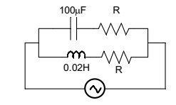
The circuit below is excited by a sinusoidal source. The value of R, in , for which the admittance of the circuit becomes a pure conductance at all frequencies is _____________.
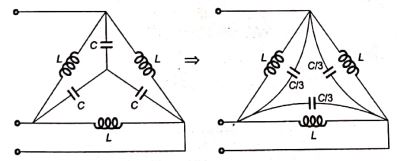
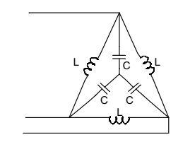
In the balanced 3-phase, 50 Hz, circuit shown below, the value of inductance (L) is 10 mH. The value of the capacitance (C) for which all the line currents are zero, in millifarads, is ___________.
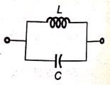
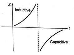
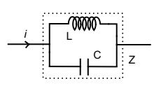
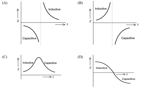
An inductor is connected in parallel with a capacitor as shown in the figure. As the frequency of current i is increased, the impedance (Z) of the network varies as
A series RLC circuit is observed at two frequencies. At =1 krad/s, we note that source voltage V results in a current . At =2 krad/s, the source voltage V results in a current . The closest values for R, L, C out of the following options are
Two magnetically uncoupled inductive coils have Q factors at the chosen operating frequency. Their respective resistances are . When connected in series, their effective Q factor at the same operating frequency is
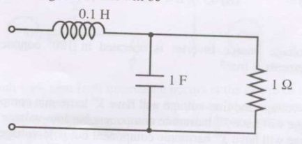
The resonant frequency for the given circuit will be
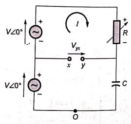
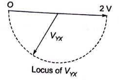
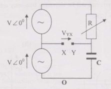
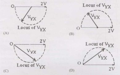
In the figure given below all phasors are with reference to the potential at point "O". The locus of voltage phasor as R is varied from zero to infinity is shown by
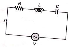
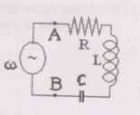
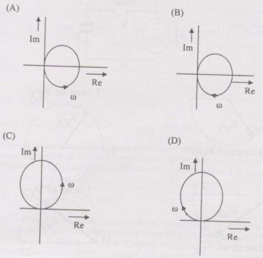
The R-L-C series circuit shown in figure is supplied from a variable frequency voltage source. The admittance-locus of the R-L-C network at terminals AB for increasing frequency is
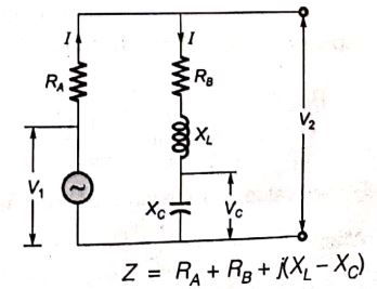
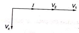
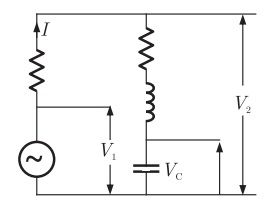
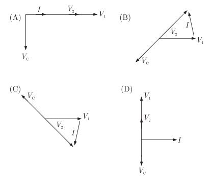
The circuit shown in the figure is energized by a sinusoidal voltage source at a frequency which causes resonance with a current of I . The phasor diagram which is applicable to this circuit is
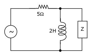
The value of Z in figure, which is most appropriate to cause parallel resonance at 500 Hz is
In the circuit of figure, the magnitudes of and are twice that of . Given that f = 50 Hz, the inductance of the coil is
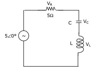
A series R-L-C circuit has R= , L= and C= . The lower half power frequency of the circuit is
In the circuit shown in figure, what value of C will cause a unity power factor at the ac source?
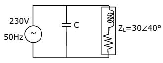
In a series RLC circuit at resonance, the magnitude of the voltage developed across the capacitor
Want unlimited AI-generated Resonance And Locus Diagrams questions?
Sign up free and practice with adaptive difficulty — Easy, Medium, Hard. New questions every session.
Start practising for free →