GATE EE · Electric Circuits
Generate GATE-level questions on Sinusoidal Steady-state analysis. Focus on: 1. Phasor representation and Impedance/Admittance. 2. Complex power (Real, Reactive, Apparent) and Power factor. 3. Node and Mesh analysis for AC circuits.
21 questions · 20 PYQs · 0 AI practice · GATE EE 2027
🎯 These are sample questions
Just sign in to unlock everything. Free for all students.
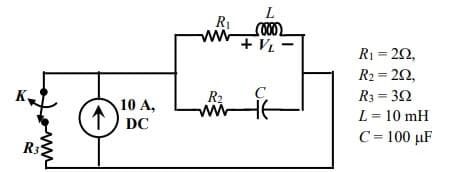
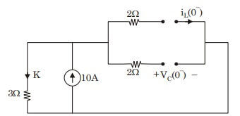
The value of parameters of the circuit shown in the figure are For time , the circuit is at steady state with the switch ' ' in closed condition. If the switch is opened at , the value of the voltage across the inductor at in Volts is _____ (Round off to 1 decimal place).
An inductor having a Q-factor of 60 is connected in series with a capacitor having a Q-factor of 240. The overall Q-factor of the circuit is ________. (round off to nearest integer)
The network shown below has a resonant frequency of 150 kHz and a bandwidth of 600 Hz. The Q-factor of the network is __________. (round off to nearest integer)
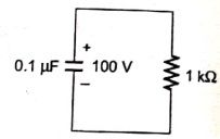
A 0.1 capacitor charged to 100 V is discharged through a 1 resistor. The time in ms (round off to two decimal places) required for the voltage across the capacitor to drop to 1V is ______
In the figure, the voltages are , and . The circuit is in sinusoidal steady state, and . , and are the average power outputs. Which one of the following statements is true?

The voltage across the circuit in the figure, and the current through it, are given by the following expressions: where radian/s. If the average power delivered to the circuit is zero, then the value of X (in Ampere) is _____ (up to 2 decimal places).

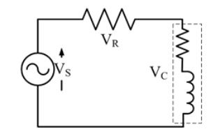
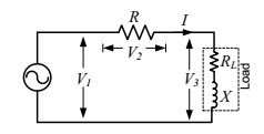
A resistance and a coil are connected in series and supplied from a single phase, 100 V, 50 Hz ac source as shown in the figure below. The rms values of plausible voltages across the resistance ( ) and coil ( ) respectively, in volts, are

The voltage (V) and current (A) across a load are as follows. , . The average power consumed by the load, in W, is___________.
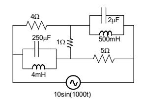
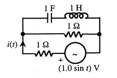
In the circuit shown below, the supply voltage is volts. The peak value of the steady state current through the 1 resistor, in amperes, is ______.

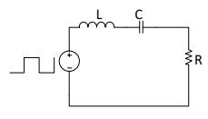
A symmetrical square wave of 50% duty cycle has amplitude of 15 V and time period of 0.4 ms. This square wave is applied across a series RLC circuit with R=5 , L=10 mH, and C=4 F. The amplitude of the 5000 rad/s component of the capacitor voltage (in Volt) is ______.

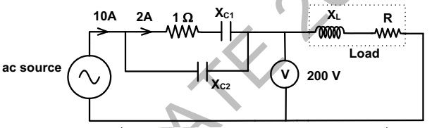
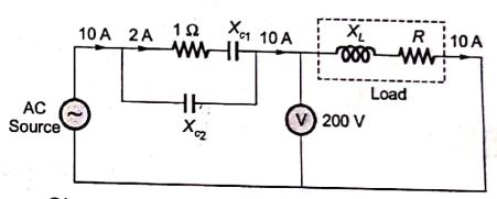
The total power dissipated in the circuit, shown in the figure, is 1 kW. The voltmeter, across the load, reads 200 V. The value of is _____.

The average power delivered to an impedance by a current 5cos(100 t+100)A is
In the circuit shown, the three voltmeter readings are 220 V , 122 V , 136 V. If , the approximate power consumption in the load is

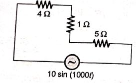
The r.m.s value of the current i(t) in the circuit shown below is

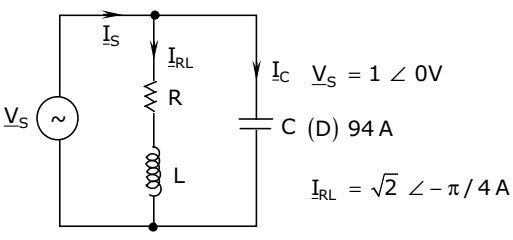
An RLC circuit with relevant data is given below. The current in the figure above is

The voltage applied to a circuit is volts and the circuit draws a current of amperes. Taking the voltage as the reference phasor, the phasor representation of the current in amperes is
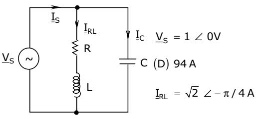
An RLC circuit with relevant data is given below. The power dissipated in the resistor R is

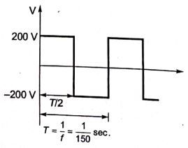
An energy meter connected to an immersion heater (resistive) operating on an AC 230 V, 50 Hz, AC single phase source reads 2.3 units (kWh) in 1 hour. The heater is removed from the supply and now connected to a 400 V peak to peak square wave source of 150 Hz. The power in kW dissipated by the heater will be
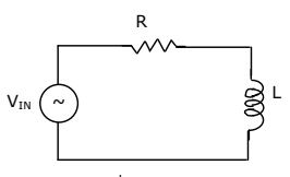
The RL circuit of the figure is fed from a constant magnitude, variable frequency sinusoidal voltage source . At 100 Hz, the R and L elements each have a voltage drop . If the frequency of the source is changed to 50 Hz, then new voltage drop across R is

The RMS value of the voltage u(t)= 3 + 4 cos (3t) is
Want unlimited AI-generated Steady State Ac Analysis questions?
Sign up free and practice with adaptive difficulty — Easy, Medium, Hard. New questions every session.
Start practising for free →