Q81NEET UG 2014MCQ
A thin semicircular conducting the ring (PQR) of radius 'r' is falling with its plane vertical in a horizontal magnetic field B, as shown in figure. The potential difference developed across the ring when its speed is v, is:

NEET UG · Physics
Generate NEET level questions on Electromagnetic Induction and Alternating Currents. Focus on NCERT concepts.
123 questions · 20 PYQs · 0 AI practice · NEET UG 2027
A thin semicircular conducting the ring (PQR) of radius 'r' is falling with its plane vertical in a horizontal magnetic field B, as shown in figure. The potential difference developed across the ring when its speed is v, is:
A transformer having efficiency of is working on V and kW power supply. If the current in the secondary coil is 6 A the voltage across the secondary coil and the current in the primary coil respectively are:
The primary of a transformer when connected to a dc battery of 10 volt draws a current of . The number of turns of the primary and secondary windings are 50 and 100 respectively. The voltage in the secondary and the current drawn by the circuit in the secondary are respectively (KN NEET 2013)
A current of 2.5 A flows through a coil of inductance . The magnetic flux linked with the coil is (KN NEET 2013)
A coil of self-inductance L is connected in series with a bulb B and an AC source. Brightness of the bulb decreases when (2013 NEET)
A wire loop is rotated in a magnetic field. The frequency of change of direction of the induced e.m.f. is (2013 NEET)
In an electrical circuit, R, L, C and ac voltage source are all connected in series. When L is removed from the circuit, the phase difference between the voltage and the current in the circuit is . If instead, C is removed from the circuit, the phase difference is again . The power factor of the circuit is (2012)
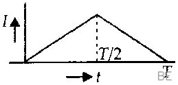
In a coil of resistance 10 Ω, the induced current developed by changing magnetic flux through it, is shown in figure as a function of time. The magnitude of change in flux through the coil in weber is (2012 Mains)

The current in the inductance is varying with time according to the plot shown in figure.Which one of the following is the correct variation of voltage with time in the coil? (2012)



An ac voltage is applied to a resistance R and an inductor!, in series. If R and the inductive reactance are both equal to , the phase difference between the applied voltage and the current in the circuit is (2011)
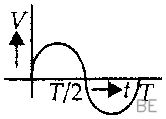
The rms value of potential difference V shown in the figure is (2011 Mains)

A coil has resistance 30 ohm and inductive reactance 20 ohm at 50 Hz frequency. If an ac source, of 200 volt, 100 Hz, is connected across the coil, the current in the coil will be(2011 Mains)
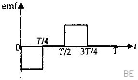
The current i in a coil varies with time as shown in the figure. The variation of induced emf with time would be (2011)



A condenser of capacity C is charged to a potential difference of . The plates of the condenser are then connected to an ideal inductor of inductance L. The current through the inductor when the potential difference across the condenser reduces to is (2010 Mains)
In the given circuit, the reading of voltmeter and are 300 volts each. The reading of the voltmeter and ammeter A are respectively (2010)

A 220 volt input is supplied to a transformer. The output circuit draws a current of 2.0 ampere at 440 volts. If the efficiency of the transformer is 80%, the current drawn b the primary windings of the transformer is (2010)
A conducting circular loop is placed in a uniform magnetic field, B = 0.025 T with its plane perpendicular to the loop.The radius of the loop is made to shrink at a constant rate of 1 mm s '1. The induced emf when the radius is 2 cm, is (2010)
A conducting circular loop is placed in a uniform magnetic field 0.04 T with its plane perpendicular to the magnetic field. The radius of the loop starts shrinking at 2 mm/s. The induced emf in the loop when the radius is 2 cm is (2009)
A rectangular, a square, a circular and an elliptical loop, all in the (x-y) plane, are moving out of a uniform magnetic field with a constant velocity, . The magnetic field is directed along the negative z-axis direction. The induced emf, during the passage of these loops, out of the field region, will not remain constant for (2009)
Power dissipated in an LCR series circuit connected to an A.C. source of emf ε is (2009)
Want unlimited AI-generated Electromagnetic Induction And Alternating Currents questions?
Sign up free and practice with adaptive difficulty — Easy, Medium, Hard. New questions every session.
Start practising for free →