Alternating Current – JEE Main PhysicsPractice Questions & PYQs
Generate JEE Main level questions on Alternating Current. Focus on LCR circuits, Resonance, and Power factor.
188 questions · 20 PYQs · 0 AI practice · JEE Main 2027
Q161JEE Main 2018MCQ
A power transmission line feeds input power at 2300 V to a step down transformer with its primary windings having 4000 turns, giving the output power at 230 V. If the current in the primary of the transformer is 5 A, and its efficiency is 90%, the output current wouldbe :[Main 16 April 2018 S1]
The efficiency (η) of a transformer is the ratio of output power to input power, defined by the formula η=VpIpVsIs, where Vp and Ip are the primary voltage and current, and Vs and Is are the secondary voltage and current. Substituting the given values η=0.9, Vp=2300 V, Vs=230 V, and Ip=5 A into the equation yields 0.9=2300×5230×Is. Rearranging the expression to isolate the secondary current gives Is=2300.9×2300×5, which simplifies to Is=45 A.
Q162JEE Main 2018MCQ
For an RLC circuit driven with voltage of amplitude vm and frequency ω0=1/LC the current exhibits resonance. The quality factor, Q is given by :[Main 8 April 2018]
The quality factor represents the sharpness of resonance in an RLC circuit, quantifying the efficiency of energy storage relative to energy dissipation. At the resonant frequency ω0, where inductive reactance perfectly balances capacitive reactance, this factor is determined by the ratio of the inductive reactance to the circuit's total resistance. Since the inductive reactance is calculated as the product of the angular frequency and the inductance, the relationship is defined as Q=Rω0L.
Q163JEE Main 2017MCQ
A sinusoidal voltage of peak value 283 V and angular frequency 320/s is applied to a series LCR circuit. Given that R=5Ω, L=25mH and C=1000μF. The total impedance, and phase difference between the voltage across the source and the current will respectively be :[Main 9 April 2017]
The total impedance Z in a series LCR circuit is calculated using the formula Z=R2+(XL−XC)2, where XL=ωL and XC=ωC1 are the inductive and capacitive reactances, respectively. Given the angular frequency ω=320 rad/s, resistance R=5Ω, inductance L=25 mH, and capacitance C=1000\muF, the reactances are determined as XL=320×25×10−3=8Ω and XC=320×10−31=3.125Ω. Substituting these values into the impedance formula yields Z=52+(8−3.125)2=25+(4.875)2≈25+23.77≈6.98Ω, which is approximately 7Ω.
The phase difference ϕ between the source voltage and the current is determined by the equation tanϕ=RXL−XC, which yields tanϕ=58−3.125=54.875=0.975. Because tan45∘=1, the value 0.975 indicates that the phase difference ϕ is approximately 45∘.
Q164JEE Main 2016MCQ
An arc lamp requires a direct current of 10 A and 80 V to function. If it is connected to a 220 V (rms), 50Hz AC supply, the series inductor needed for it to work is close to :[Main 2016]
An arc lamp operates as a resistor because its fixed voltage and current requirements of 80 V and 10 A allow us to calculate its resistance as R=80/10=8Ω. When this lamp is connected to a 220 V AC supply while maintaining the same 10 A current, the total impedance of the circuit must be Z=220/10=22Ω.
Since the circuit consists of a series resistor and inductor, the impedance follows the relationship Z2=R2+XL2, where XL=ωL. Substituting the known values leads to 222=82+(ωL)2, which simplifies to 484=64+(ωL)2, or (ωL)2=420. With the angular frequency defined as ω=2πf=2⋅π⋅50=100π rad/s, solving for L yields L=420/(100π), resulting in an inductance of approximately 0.065 H.
Q165JEE Main 2016MCQ
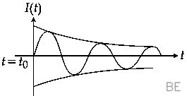
A series LR circuit is connected to a voltage source with V(t)=V0sinΩt.After very large time, current I(t) behaves as (t0>>L/R):[Main 9 Apr 2016]
When an alternating current source is connected to a series circuit containing a resistor and an inductor, the system eventually reaches a steady state once the transient effects subside after a sufficiently long duration. In this regime, the current oscillates at the same frequency as the driving voltage, but the inductor introduces a phase lag due to its reactance. This creates a current profile defined by I(t)=I0sin(Ωt−ϕ), which manifests as a sinusoidal wave shifted in time relative to the voltage source.
Q166JEE Main 2015MCQ
An inductor (L = 0.03 H) and a resistor (R = 0.15 kΩ) are connected in series to a battery of 15V EMF in a circuit shown. The key K1 has been kept closed for a long time. Then at t=0,K1 is opened and key K2 is closed simultaneously. At t = 1 ms, the current in the circuit will be: (e5≅150)[Main 2015]
When the first key remains closed for a long time, the inductor acts as a simple wire, allowing the steady current to be determined by the electromotive force divided by the total resistance. With a battery of 15 V and resistance of 150 Ω, the initial current is I0=15/150=0.1 A.
Opening the first key while simultaneously closing the second key transforms the setup into an isolated inductor-resistor loop, where the stored magnetic energy dissipates and the current decays exponentially according to the expression i(t)=I0e−Rt/L
Calculating the exponent factor for a time of 0.001 s gives Rt/L=(150×0.001)/0.03=5. Substituting this value into the decay equation yields i=0.1×e−5. Using the given approximation e5≈150, the current becomes i=0.1/150 A, which results in 0.67 mA.
Q167JEE Main 2015MCQ
An LCR circuit is equivalent to a damped pendulum. In an LCR circuit the capacitor is charged to Q0then connected to the L and R as shown.If a student plots graphs of the square of maximum charge Qmax2 on the capacitor with time (t) for two different values L1 and L2(L1>L2) of L then which of the following represents this graph correctly? (Plots are schematic and not drawn to scale) [Main 2015]
An LCR circuit undergoing damped oscillations acts analogously to a physical pendulum losing energy due to friction, where the resistance R serves as the damping agent and the inductance L provides the electrical inertia. Because L1>L2, the circuit with the larger inductance effectively resists the decay of current and charge more strongly, resulting in a slower rate of energy dissipation compared to the circuit with the smaller inductance L2. Consequently, the square of the maximum charge Qmax2 on the capacitor, which is directly proportional to the stored energy at each oscillation peak, decreases more gradually over time for L1 than for L2. This means the decay curve for L1 will remain consistently above the curve for L2 throughout the process, reflecting the slower rate of energy dissipation in the higher-inductance circuit.
Q168JEE Main 2014MCQ
In the circuit shown here,the point 'C' is kept connected to point 'A' till the current flowing through the circuit becomes constant.Afterward,Suddenly,point 'C' is disconnected from point 'A' and connected to point 'B' at time t=0.Ratio of the voltage across resistance and the inductor at t=L/R will be equal to:[Main 2014]
When point C is moved to point B, the circuit effectively places the resistor and the inductor in a parallel arrangement. Because these components are connected in parallel, the instantaneous potential difference across the resistor must exactly match the potential difference across the inductor. This equality holds at all times, so the ratio of the voltage across the resistance to the voltage across the inductor is 1, even at the specific time t=L/R.
Q169JEE Main 2013MCQ
In an LCR circuit as shown below both switches are open initially. Now switch S1 is closed,S2 kept open. (q is charge on the capacitor and τ = RC is capacitive time constant). Which of the following statement is correct? [Main 2013]
When switch S1 is closed in an RC circuit, the capacitor charges according to the standard exponential function q(t)=CV(1−e−t/τ), where τ denotes the time constant RC. To determine the charge at t=2τ, we substitute this value for the time variable t within the charging equation. This substitution simplifies the exponent to −2τ/τ, which evaluates to −2. Consequently, the charge stored on the capacitor at this specific instant is calculated as q=CV(1−e−2).
Q170JEE Main 2011MCQ
A resistor ′R′ and 2μF capacitor in series is connected through a switch to 200V direct supply. Across the capacitor is a neon bulb that lights up at 120V. Calculate the value of R to make the bulb light up 5s after the switch has been closed. (log102.5=0.4)
The behavior of a charging capacitor in a series RC circuit is governed by the equation V=V0(1−e−t/RC), where V represents the capacitor voltage at time t, V0 is the constant supply voltage, R is the series resistance, and C is the capacitance. Given that the neon bulb ignites at 120V when the supply is 200V, the capacitor must reach 120V at t=5s. Inserting these values into the charging equation gives 120=200(1−e−5/(R×2×10−6)), which simplifies to 0.6=1−e−5/(R×2×10−6) and further to e−5/(R×2×10−6)=0.4.
Inverting the exponential term results in e5/(R×2×10−6)=2.5. Taking the natural logarithm on both sides provides the expression R×2×10−65=ln(2.5)
Using the conversion ln(x)=2.303log10(x), the natural logarithm becomes 2.303×0.4, which is approximately 0.9212. Isolating R in the equation yields R=5/(0.9212×2×10−6), resulting in a resistance of approximately 2.71×10⁶Ω.
Q171JEE Main 2011MCQ
A fully charged capacitor C with initial charge q0 is connected to a coil of self inductance L at t=0. The time at which the energy is stored equally between the electric and the magnetic fields is :
In an LC circuit, total energy continuously oscillates between the electric field of the capacitor and the magnetic field of the inductor. When these energies are shared equally, the electric energy accounts for half of the system's total initial energy, leading to the condition 21Cq2=21(21Cq02). Simplifying this relationship yields q=2q0, which, when substituted into the oscillation formula q=q0cos(ωt), requires cos(ωt)=21. With the angular frequency defined as ω=LC1, solving the phase ωt=4π results in the time t=4πLC.
Q172JEE Main 2010MCQ
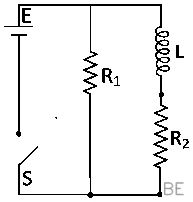
In the circuit shown below, the key K is closed at t=0. The current through the battery is
An inductor acts as an open circuit immediately after a switch is closed because it resists any instantaneous change in current, while it behaves as a simple conducting wire once the circuit reaches a steady state. At t=0, the path containing the inductor is effectively blocked, ensuring all current passes solely through R2 with a value of R2V. By the time t=∞, the inductor functions as a perfect conductor, connecting resistors R1 and R2 in parallel to create an equivalent resistance of R1+R2R1R2, resulting in a battery current of R1R2V(R1+R2).
Q173JEE Main 2010MCQ
In a series LCR circuit R=200Ω and the voltage and the frequency of the main supply is 220V and 50Hz respectively. On taking out the capacitance from the circuit the current lags behind the voltage by 30∘. On taking out the inductor from the circuit the current leads the voltage by 30∘. The power dissipated in the LCR circuit is
The power dissipated in an alternating current circuit containing a resistor, inductor, and capacitor depends on the total impedance of the network, as the resistor is the only component that consumes real power. By analyzing the circuit conditions when components are removed, the individual reactances can be determined. When the capacitor is taken out, the circuit becomes an LR series combination where the current lags behind the voltage by 30∘, a relationship defined by tan(30∘)=RXL, which gives the inductive reactance XL=200tan(30∘)=3200Ω. Similarly, removing the inductor creates a CR series combination where the current leads the voltage by 30∘, leading to tan(30∘)=RXC and yielding a capacitive reactance XC=3200Ω.
In the complete LCR circuit, the impedance Z is defined by Z=R2+(XL−XC)2. Since the reactances XL and XC are equal, the reactive term cancels out, leaving the total impedance equal to the resistance, Z=200Ω. The power dissipated is determined by the applied voltage and the impedance, allowing the formula to be simplified as follows:
P=Z2V2R=RV2=2002202=242 W
Q174JEE Main 2009MCQ
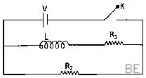
An inductor of inductance L=400mH and resistors of resistance R1=2Ω and R2=2Ω are connected to a battery of emf 12V as shown in the figure. The internal resistance of the battery is negligible. The switch S is closed at t=0. The potential drop across L as a function of time is :
When a battery is connected to an inductor and a resistor in series, the inductor initially acts as an open circuit to oppose the rapid surge of current, creating a back electromotive force that makes the potential drop across it equal to the battery's total voltage at the instant the switch is closed. As time progresses, the current through this inductor-resistor branch increases following the standard transient growth equation, which causes the voltage across the inductor to decay exponentially toward zero as the current approaches a steady state.
The current in the branch containing L and R2 follows the relationship i=R2E(1−e−(R2/L)t). By differentiating this expression with respect to time, the rate of change is determined to be dtdi=LEe−(R2/L)t. Multiplying this rate by the inductance L yields the potential drop across the inductor, expressed as VL=Ee−(R2/L)t. Substituting the provided values, where the electromotive force is 12 V, the resistance is 2 Ω, and the inductance is 0.4 H, the exponent term becomes −(2/0.4)t, which simplifies to −5t. Consequently, the potential drop as a function of time is 12e−5t V.
Q175JEE Main 2007MCQ
In an a.c. circuit the voltage applied is E=E0sinωt. The resulting current in the circuit is I=I0sin(ωt−2π). The power consumption in the circuit is given by
The average power consumed in an AC circuit is determined by the expression P=ErmsIrmscosϕ, where ϕ represents the phase difference between the voltage and the current. Comparing the provided expressions E=E0sinωt and I=I0sin(ωt−2π), it is clear that the phase difference is ϕ=2π. Since the power factor term cosϕ evaluates to cos(2π)=0, the total power consumption in the circuit is zero.
Q176JEE Main 2006MCQ
In a series resonant LCR circuit, the voltage across R is 100 volts and R=1kΩ with C=2μF. The resonant frequency ω is 200rad/s. At resonance the voltage across L is
The behavior of a series resonant LCR circuit is governed by the condition where inductive reactance perfectly cancels capacitive reactance, making the total impedance purely resistive. Given the voltage across the resistor is 100 V and the resistance is 1000 ohms, the circuit current is determined by I=1000100=0.1 A. At resonance, the inductive reactance XL is equal to the capacitive reactance, which is defined as XL=ωC1. By substituting the given angular frequency of 200 rad/s and capacitance of 2 ×10⁻⁶ F, the reactance becomes XL=200×2×10−61=2500 ohms. Consequently, the voltage across the inductor is calculated by multiplying the circuit current by this inductive reactance, VL=0.1×2500=250 V.
Q177JEE Main 2006MCQ
In an AC generator, a coil with N turns, all of the same area A and total resistance R, rotates with frequency ω in a magnetic field B. The maximum value of emf generated in the coil is
Faraday's Law of Induction dictates that the electromotive force in a rotating coil depends on the time rate of change of the magnetic flux, which is defined as ϕ=NBAcos(ωt). Differentiating this flux with respect to time gives the instantaneous induced electromotive force as e=NBAωsin(ωt). Since the maximum possible value of the sine term is one, the peak induced voltage produced by the generator is NABω.
Q178JEE Main 2005MCQ
The phase difference between the alternating current and emf is 2π. Which of the following cannot be the constituent of the circuit?
The phase difference in an alternating current circuit is dictated by the combination of its resistive and reactive elements. Since an R-L circuit inherently contains resistance, the phase difference is constrained to lie strictly between 0 and 2π, making it impossible for this configuration to achieve a shift of exactly 2π. Pure inductive, pure capacitive, and LC circuits lack this resistive component, allowing them to produce the specific phase difference of 2π.
Q179JEE Main 2005MCQ
The self inductance of the motor of an electric fan is 10H. In order to impart maximum power at 50Hz, it should be connected to a capacitance of
Maximum power in an AC circuit is achieved at electrical resonance, where the inductive reactance of the motor is exactly countered by the capacitive reactance. These reactances are defined as XL=2πfL and XC=2πfC1 respectively, where f is frequency and L is inductance. Equating XL=XC results in the resonance frequency condition, which can be rearranged to solve for capacitance:
C=4π2f2L1
Substituting the provided values where frequency is 50 Hz and inductance is 10 H gives C=4π2×502×101. Computing the denominator leads to 4π2×2500×10, which simplifies to 100,000π2. By applying the common approximation π2≈10, the calculation results in 1×10⁻⁶ F, which corresponds to a capacitance of 1 µF.
Q180JEE Main 2005MCQ
A circuit has a resistance of 12ohm and an impedance of 15ohm. The power factor of the circuit will be
In alternating current circuits, the power factor describes the phase relationship between voltage and current and is calculated as the ratio of the circuit's resistance to its total impedance. This relationship is defined by the following equation:
cosϕ=ZR
By substituting the known values, where the resistance is 12 ohm and the impedance is 15 ohm, the calculation requires dividing 12 by 15. Performing this division yields a power factor of 0.8.
Want unlimited AI-generated Alternating Current questions?
Sign up free and practice with adaptive difficulty — Easy, Medium, Hard. New questions every session.