Q141JEE Main 2020MCQ
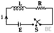
A series L-R circuit is connected to a battery of . If the circuit is switched on at ,then the time at which the energy stored in the inductor reaches times of its maximum value, is :
JEE Main · Physics
Generate JEE Main level questions on Alternating Current. Focus on LCR circuits, Resonance, and Power factor.
188 questions · 20 PYQs · 0 AI practice · JEE Main 2027
A series L-R circuit is connected to a battery of . If the circuit is switched on at ,then the time at which the energy stored in the inductor reaches times of its maximum value, is :
A (rms) source is connected to a resistance of an inductance of and a capacitance of all in series. The time in which the resistance (heat capacity ) will get heated by . (assume no loss of heat to the surroundings) is close to :
An emf of 20 V is applied at time to a circuit containing in series 10 mH inductor and 5 Ω resistor. The ratio of the currents at time and at is close to : (Take )
An AC circuit has and connected in series. The quality factor of the circuit is :
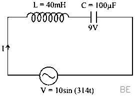
In LC circuit the inductance L = 40 mH and capacitance C = 100 µF. If a voltage V(t) = 10sin(314 t) is applied to the circuit, the current in the circuit is given as :
An inductance coil has a reactance of . When an AC signal of frequency is applied to the coil, the applied voltage leads the current by The self-inductance of the coil is :
A LCR circuit behaves like a damped harmonic oscillator. Comparing it with a physical springmass damped oscillator having damping constant 'b', the correct equivalence would be: [7-Jan-2020 Shift 1]
In a scries LR circuit, power of is dissipated from a source of . The power factor of the circuit is In order to bring the power factor to unity, a capacitor of value is added in series to the and . Taking the value of as then value of is
A coil of self inductance 10mH and resistance is connected through a switch to a battery of internal resistance .After the switch is closed, the time taken for the current to attain 80% of the saturation value is:{take ln5 =1.6}
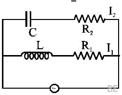
In the above circuit, C = µF , = 20 Ω, L = H and = 10 Ω. Current in L - path is and in C - path it is . The voltage of A.Csource is given by V = 200 sin (100t) volts. The phase difference between and is :
A transformer consisting of 300 turns in the primary and 150 turns in the secondary gives output power of 2.2kw. if the current in the secondary coil is 10A, then the input voltage and current in the primary Coil are:
A power transmission line feeds input power at 2300 V to a step down transformer with its primary windings having 4000 turns. The output power is delivered at 230 V bv the transformer. If the current in the primary of the transformer is 5A and its efficiency is 90%, the output current would be :
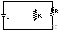
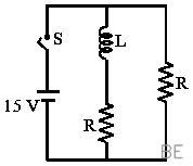
In the figure shown, a circuit contains two identical resistors with resistance R = 5Ω and an inductance with L = 2mH. An ideal battery of 15 V is connected in the circuit. What will be the current through the battery long after the switch is closed?
An alternating voltage volt is applied to a purely resistive load of . The time taken for the current to rise from half of the peak value to the peak value is:
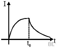
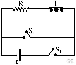
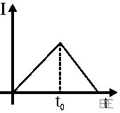
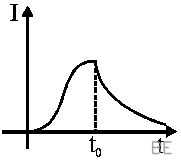
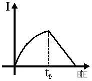
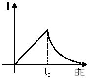
In the circuit shown, the switch is closed at time t = 0 and the switch is kept open. At some later time (), the switch is opened and is closed. The behavious of the current I as a function of time 't' is given by :
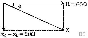
A series AC circuit containing an inductor (20 mH), a capacitor (120 µF) and a resistor (60Ω) is driven by an AC source of 24 V/50 Hz. The energy dissipated in the circuit in 60 s is :
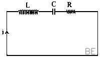
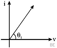
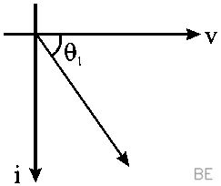
A circuit connected to an ac source of emf with t in seconds, gives a phase difference of between the emf e and current i. Which of the following circuits will exhibit this ?
Consider the LR circuit shown in the figure. If the switch is closed at then the amount of charge that passes through the battery between and is:
In an a.c. circuit, the instantaneous e.m.f. and current are given by In one cycle of a.c., the average power consumed by the circuit and the wattless currentare, respectively :[Main 8 April 2018]
An ideal capacitor of capacitance 0.2µFis charged to a potential difference of 10 V. The charging battery is then disconnected. The capacitor is then connected to an ideal inductor of self inductance 0.5 mH. The current at a time when the potential difference across the capacitor is 5 V, is :[Main 15 April 2018 S1]
Want unlimited AI-generated Alternating Current questions?
Sign up free and practice with adaptive difficulty — Easy, Medium, Hard. New questions every session.
Start practising for free →