Transformers – GATE EE Electrical MachinesPractice Questions & PYQs
Generate GATE-level questions on Transformers. Focus on:
1. Equivalent circuit, Phasor diagram, and Efficiency/Regulation.
2. Losses: Hysteresis and Eddy current losses.
3. Three-phase transformers: Star/Delta connections, Parallel operation, and Autotransformers.
65 questions · 20 PYQs · 0 AI practice · GATE EE 2027
🎯 These are sample questions
Get the full Transformers experience — 100% free
✓ Attempt tracking & analytics
✓ Timer & exam-mode simulation
✓ Adaptive difficulty (Easy → Hard)
✓ Bookmarks, notes & mistake review
Just sign in to unlock everything. Free for all students.
Which one of the following options represents possible voltage polarities in a single phase two winding transformer? Here, Vp is the applied primary voltage, Ep is the induced primary voltage, Vs is the open circuit secondary voltage, and Es is the induced secondary voltage.
When the winding c−d of the singlephase, 50 Hz , two winding transformer is supplied from an AC current source of frequency 50Hz , the rated voltage of 200V (rms), 50Hz . is obtained at the open-circuited terminals a-b. The cross sectional area of the core 5000mm2 and the average core length traversed by the mutual flux is 500mm . The maximum allowable flux density in the core is Bmax=1Wb/m2 and the relative permeability of the core material is 5000 . The leakage impedance of the winding a−b and winding c-d at 50Hz are (5+j100π×0.16)Ω and (11.5+j100π×0.36)Ω , respectively. Considering the magnetizing characteristics to be linear and neglecting core loss, the self-inductance of the winding a−b in millihenry is ____ (Round off to 1 decimal place).
L= Mutual + leakage =2.05843+0.16=2.21843H or 2218.43mH
Q3GATE 2021MCQ
In a single-phase transformer, the total iron loss is 2500W at nominal voltage of 440V and frequency 50Hz . The total iron loss is 850W at 220V and 25Hz . Then, at nominal voltage and frequency, the hysteresis loss and eddy current loss respectively are
Wi1Wi2Wi3Rθ3⇒2500 or, f2500or,502500and25850=2500W at 440V,50Hz=850W at 220V,25Hz=Re3+PH3 at 440V,50Hz=?,Ph3=?,fv=constant=Af+Bf2=A+Bf=A+B(50)=A+B(25){50400=25220= Constant }…(i)…(ii)
Solving (i) and (ii), we get
25BBand from (i),ASo, at50HzPhPe=502500−25850=502500−1700=50800=16=2516=50−2516×50=50−32=18=Af=18×50=900W=Bf=(2516)×(50)2=1600W
Q4GATE 2020MCQ
The figure below shows the per-phase Open Circuit Characteristics (measured in V) and Short Circuit Characteristics (measured in A) of a 14 kVA, 400 V, 50 Hz, 4-pole, 3-phase, delta connected alternator, driven at 1500 rpm. The field current, If is measured in A. Readings taken are marked as respective (x,y) coordinates in the figure. Ratio of the unsaturated and saturated synchronous impedances ( Zs(unsat)/Zs(sat) ) of the alternator is closest to
At IfFrom SCCat If∴IfZs,unsaturated For Zs, saurated:when, VOCIfFrom SCC, IfZs,saturated Hence,Zs, saturated Zs,unsaturated =2A,VOC=210V=4A,ISC=20A=2A,ISC=10A=ISCVOCIf=const.=10210=21Ω=Vrated=400V=8A=8A,ISC=40A=40400=10Ω=1021=2.1Ω
Q5GATE 2020NAT
Windings 'A', 'B' and 'C' have 20 turns each and are wound on the same iron core as shown, along with winding 'X' which has 2 turns. The figure shows the sense (clockwise/ anti-clockwise) of each of the windings only and does not reflect the exact number of turns, If windings 'A', 'B' and 'C' are supplied with balanced 3-phase voltages at 50 Hz and there is no core saturation, the no-load RMS voltage (in V, rounded off to 2 decimal places) across winding 'X' is _________ .
As per GATE official answer key MTA (Marks to ALL) VX=202(230∠0∘−230∠120∘−230∠−120∘)=46∠0∘V
Q6GATE 2020NAT
A conducting square loop of side length 1 m is placed at a distance of 1 m from a long straight wire carrying a current l=2 A as shown below. The mutual inductance, in nH (rounded off to 2 decimal places), between the conducting loop and the long wire is __________.
ϕϕBMagnetic fluxϕϕϕMMM∝I=MI=2πρμoIaϕ^(B due to infinite long line) crossing square loop is=∫∫B⋅ds=∫∫2πρμoIaϕ^⋅(dρdz)aϕ^=2πμ0I∫ρ=12ρdρ∫z=01dz=2πμoI(lnρ)ρ=12(z)z=01=2πμoI(ln2)=Iϕ=2πϕo(ln2)=2π4π×10−7(ln2)=1.386×10⁻⁷Henry≃138.63nH
Q7GATE 2020NAT
A single-phase, 4 kVA, 200 V/100 V, 50 Hz transformer with laminated CRGO steel core has rated no-load loss of 450 W. When the high-voltage winding is excited with 160 V, 40 Hz sinusoidal ac supply, the no-load losses are found to be 320 W. When the highvoltage winding of the same transformer is supplied from a 100 V, 25 Hz sinusoidal ac source, the no-load losses will be _________W (rounded off to 2 decimal places).
200V,50Hz,Pc160V,40Hz,Pc100V,25Hz,]Pcfv=constantSo, Pc450320From (i) and (ii),5045040320Equation (iii)-(iv),(9−8)BANow at 100V,25 Hz,Pc=450Watt=320Watt=?Watt=50200=40160=25100=Af+Bf2=A×(50)+B×(50)2...(i)=A×(40)+B×(40)2...(ii)=A+B(50)...(iii)=A+B(40)...(iv)=B(10)=101=9−101×50=4=4×25+101×(25)2=100+62.5=162.50Watt
Q8GATE 2019NAT
A single-phase transformer of rating 25 kVA, supplies a 12 kW load at power factor of 0.6 lagging. The additional load at unity power factor in kW (round off to two decimal places) that may be added before this transformer exceeds its rated kVA is __________.
Voltage regulation =VNLVNL−VFL×100=100100−95×100=5%
Q10GATE 2018NAT
A 3-phase 900kVA, 3kV/3kV(Δ/Y) , 50Hz transformer has primary (high voltage side) resistance per phase of 0.3 Ω and secondary (low voltage side) resistance per phase of 0.02 Ω . Iron loss of the transformer is 10 kW. The full load % efficiency of the transformer operated at unity power factor is _______ (up to 2 decimal places).
Primary line current, Il1=3×3000900×1000=173.2A Primary phase current, Iph1=100A Secondary line current, Il2=3×1732900×1000=300A Secondary phase current Iph2=300A Cu loss of H.V. side =3×I12R1=3(100)2(0.3)=9000Watts Cu loss of L.V. side =3×22×R2=3(300)2(0.02)=5400Watts Full load efficiency at u.p.f.
A single-phase 100 kVA, 1000 V / 100 V, 50 Hz transformer has a voltage drop of 5% across its series impedance at full load. Of this, 3% is due to resistance. The percentage regulation of the transformer at full load with 0.8 lagging power factor is
Percent voltage regulation =(E2I2R02×100)cosϕ2±(E2I2X02×100)sinϕ2%VR.=Vrcosϕ2±Vxsinϕ2 (where, '+' lag p.f. and '-' lead p.f.) At full load: Given, Vr=3% Impedance drop, Vz=5%∴ Reluctance drop, Vx=52−32=4% Voltage regulation at full load at 0.8 p.f. lagging V.R.=3(0.8)+4(0.6)=4.8%
Q12GATE 2017NAT
If the primary line voltage rating is 3.3 kV (Y side) of a 25 kVA. Y- Δ transformer (the per phase turns ratio is 5:1), then the line current rating of the secondary side (in Ampere) is_____.
A three-phase, three winding Δ/Δ/Y (1.1kV/6.6kV/400 V) transformer is energized from AC mains at the 1.1 kV side. It supplies 900 kVA load at 0.8 power factor lag from the 6.6 kV winding and 300 kVA load at 0.6 power factor lag from the 400 V winding. The RMS line current in ampere drawn by the 1.1 kV winding from the mains is _______.
A single-phase, 2 kVA, 100/200 V transformer is reconnected as an auto-transformer such that its kVA rating is maximum. The new rating, in kVA, is ______.
Three single-phase transformers are connected to form a delta-star three-phase transformer of 110 kV/ 11 kV. The transformer supplies at 11 kV a load of 8 MW at 0.8 p.f. lagging to a nearby plant. Neglect the transformer losses. The ratio of phase currents in delta side to star side is
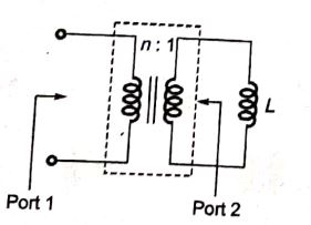
At port 1 i.e. high voltage side impedance will be high and current will be low. So, n2L .
Q17GATE 2016NAT
A single-phase 400 V, 50 Hz transformer has an iron loss of 5000 W at the rated condition. When operated at 200 V, 25 Hz, the iron loss is 2000 W. When operated at 416 V, 52 Hz, the value of the hysteresis loss divided by the eddy current loss is ______.
A single-phase, 22 kVA, 2200 V/ 220 V, 50 Hz, distribution transformer is to be connected as an auto-transformer to get an output voltage of 2420 V. Its maximum kVA rating as an autotransformer is
22 KVA, 2200 V/220 V, 50Hz Distribution transformer is to be connected as on auto transformer to get an output voltage of 2420V. (kVA)maximum as an auto transformer=? as voltage rating is 2420 i.e. (2200+220)V additive polarity,
Two three-phase transformers are realized using single-phase transformers as shown in the figure. The phase difference (in degree) between voltages V1andV2 is _______.
A 200/400 V, 50 Hz, two-winding transformer is rated at 20 kVA. Its windings are connected as an auto-transformer of rating 200/600 V. A resistive load of 12 Ω is connected to the high voltage (600 V) side of the auto-transformer. The value of equivalent load resistance (in Ohm) as seen from low voltage side is _____.