Q1GATE 2025MCQ
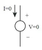
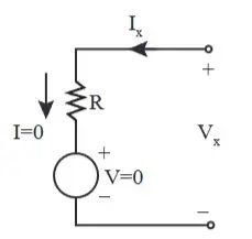
A nullator is defined as a circuit element where the voltage across the device and the current through the device are both zero. A series combination of a nullator and a resistor of value , will behave as a
GATE EE · Analog Electronics
Generate GATE-level questions on advanced Analog topics. Focus on: 1. 555 Timer applications (Astable/Monostable). 2. Voltage regulators (IC 78xx/79xx) and Power amplifiers (Class A, B, AB). 3. Specialized circuits like Logarithmic amplifiers and peak detectors.
8 questions · 8 PYQs · 0 AI practice · GATE EE 2027
🎯 These are sample questions
Just sign in to unlock everything. Free for all students.
A nullator is defined as a circuit element where the voltage across the device and the current through the device are both zero. A series combination of a nullator and a resistor of value , will behave as a
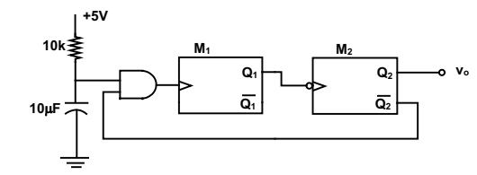
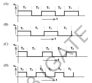
Two monoshot multivibrators, one positive edge triggered and another negative edge triggered , are connected as shown in figure The monoshots and when triggered produce pulses of width and respectively, where . The steady state output voltage of the circuit is
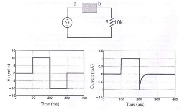
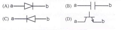
The following circuit has a source voltage as shown in the graph. The current through the circuit is also shown. The element connected between a and b could be
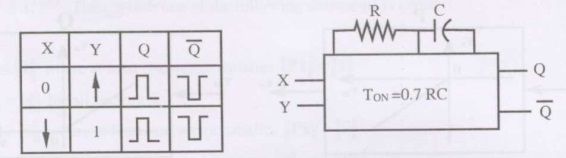
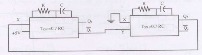
The truth table of monoshot shown in the figure is given in the table below : Two monoshots, one positive edge triggered and other negative edge triggered, are connected shown in the figure, The pulse widths of the two monoshot outputs are and respectively. The frequency and the duty cycle of the signal at will respectively be
IC 555 in the adjacent figure is configured as an astable multi-vibrator. It is enabled to to oscillate at t=0 by applying a high input to pin 4. The pin description is : 1 and 8-supply; 2-trigger; 4-reset; 6-threshold 7-discharge. The waveform appearing across the capacitor starting from t=0, as observed on a storage CRO is
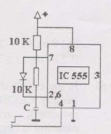
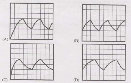
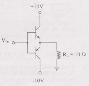
The input signal shown in the figure is a 1 kHz square wave voltage that alternates between +7 V and -7 V with a 50% duty cycle. Both transistor have the same current gain which is large. The circuit delivers power to the load resistor . What is the efficiency of this circuit for the given input ? choose the closest answer.
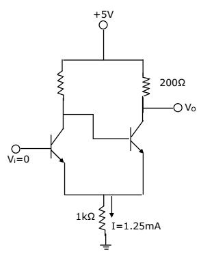
In the Schmitt trigger circuit shown in figure, if = 0.1V, the output logic low level ( ) is
The circuit of figure shows a 555 Timer IC connected as an astable multivibrator. The value of the capacitor C is 10 nF. The values of the resistors for a frequency of 10 kHz and a duty cycle of 0.75 for the output voltage waveform are

Want unlimited AI-generated Miscellaneous questions?
Sign up free and practice with adaptive difficulty — Easy, Medium, Hard. New questions every session.
Start practising for free →