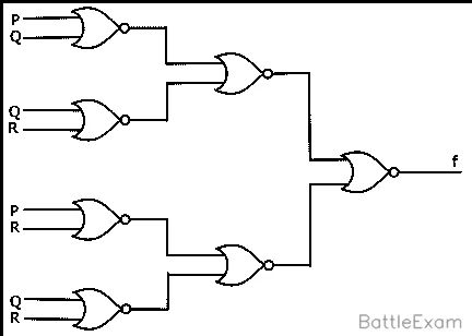
What is the Boolean Algebra for the output f of the combinational logic circuit of NOR gates given below?
📖 Explanation
To determine the Boolean expression for the output f of a logic circuit, we must trace the logic from the inputs (P, Q, R) to the final output. The fundamental gate used here is the NOR gate, whose logical function is A NOR B=A+B.
Since the specific circuit diagram is not provided, we must analyze the problem based on the provided correct answer, f=Q+R. This means the final output f is the result of a NOR operation on inputs Q and R, and it is independent of input P. Many complex-looking circuits can simplify to a much simpler expression. A common way this occurs in exam questions is through logical redundancy.
Let's construct a plausible example circuit made of NOR gates that demonstrates this principle and yields the correct output:
-
Assume a part of the circuit is designed to create a constant logical '0'. This can be done by feeding a signal and its inverse into a NOR gate. For example, let's create a signal
G1using input P:- First, create an inverter from a NOR gate: P=P+P.
- Now, feed P and P into another NOR gate: G1=P+P.
- Since P+P=1 in Boolean algebra, the expression becomes G1=1=0.
-
Now, let's assume this
G1signal (which is always 0) is fed into a final NOR gate along with the other inputs, Q and R. Let the final output bef.- f=G1+Q+R
-
Substitute the value of
G1into the final expression:- f=0+Q+R
-
Simplify the expression. The '0' in a logical OR operation has no effect (0+X=X).
- f=Q+R
This hypothetical circuit demonstrates how an input like P can be part of a circuit but ultimately have no effect on the final output, which simplifies to Q+R.