This problem involves finding an initial value before a percentage increase over time, which is a common application of compound growth principles. We need to find the population 2 years ago (P0) given the current population (P=11,02,500), an annual growth rate (r=5%), and the time period (n=2 years).
The standard formula for compound growth is: P=P0(1+100r)n
To find the population 2 years ago (P0), we rearrange the formula: P0=(1+100r)nP
Now, let's plug in the values and calculate:
First, convert the percentage rate to a decimal: 1005=0.05.
Next, add 1 to the decimal rate: 1+0.05=1.05.
Then, calculate the growth factor for 2 years: (1.05)2=1.05×1.05=1.1025.
Finally, divide the current population by this growth factor to find P0: P0=1.102511,02,500 P0=10,00,000
The population of the city 2 years ago was 10,00,000.
Q2GATE 2021MCQ1MGeneral Aptitude
p and q are positive integers and qp+pq=3, then, q2p2+p2q2=
This problem tests our ability to manipulate algebraic expressions involving fractions. We are given p and q are positive integers and the equation: qp+pq=3
Our goal is to find the value of: q2p2+p2q2
Let's simplify by substituting x=qp. This means x1=pq.
The given equation transforms to: x+x1=3
The expression we need to find becomes: (qp)2+(pq)2=x2+(x1)2=x2+x21
We can use the algebraic identity (a+b)2=a2+b2+2ab. Let a=x and b=x1: (x+x1)2=x2+(x1)2+2(x)(x1)
Simplify the term 2(x)(x1): 2(x)(x1)=2×xx=2×1=2
So, the identity becomes: (x+x1)2=x2+x21+2
We know that x+x1=3. Substitute this value into the equation: (3)2=x2+x21+2 9=x2+x21+2
To find x2+x21, subtract 2 from both sides: x2+x21=9−2 x2+x21=7
Since x2+x21=q2p2+p2q2, the value we are looking for is 7.
Q3GATE 2021MCQ1MGeneral Aptitude
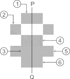
The least number of squares that must be added so that the line P-Q becomes the line of symmetry is ________.
To make the line P−Q a line of symmetry, the figure must be identical on both sides of the line. We need to add squares to one side such that it mirrors the existing squares on the other side. By visually inspecting the given figure and adding squares to complete this mirror image, we find that a total of 6 squares must be added to achieve symmetry.
Q4GATE 2021MCQ1MGeneral Aptitude
Nostalgia is to anticipation as _______ is to ________. Which one of the following options maintains a similar logical relation in the above sentence?
This analogy question tests our understanding of relationships between words. The core relationship here is one of *temporal direction*.
**Analyze the given pair:**
* **Nostalgia** is a feeling focused on the **past**. We experience nostalgia *for* something that has already happened.
* **Anticipation** is a feeling focused on the **future**. We anticipate something *that is going to happen*.
* So, the relationship is: **Past-oriented emotion : Future-oriented emotion**.
**Evaluate the options based on this temporal direction:**
* A. **Present : Past** − This doesn't match the "past : future" directional flow.
* B. **Future : Past** − This is the reverse of our required "past : future" flow.
* C. **Past : Future** − This directly mirrors the "past-oriented : future-oriented" relationship established by Nostalgia : Anticipation.
* D. **Future : Present** − This doesn't match the "past : future" directional flow.
**Conclusion:** The option that maintains the same logical relation (Past-oriented : Future-oriented) is **C. Past, future**. Therefore, Nostalgia is to anticipation as Past is to Future.
Q5GATE 2021MCQ1MGeneral Aptitude
Consider the following sentences: (i) I woke up from sleep. (ii) I woked up from sleep. (iii) I was woken up from sleep. (iv) I was wokened up from sleep. Which of the above sentences are grammatically CORRECT?
To identify the grammatically correct sentences, we need to understand the principal forms of the verb 'wake': Base Form: wake; Past Simple: woke; Past Participle: woken.
* Sentence (i) "I woke up from sleep." uses 'woke', which is the correct simple past tense of 'wake', making it grammatically correct.
* Sentence (ii) "I woked up from sleep." uses 'woked', an incorrect past tense form; the correct form is 'woke', so this sentence is grammatically incorrect.
* Sentence (iii) "I was woken up from sleep." correctly uses 'was woken', which is the past tense passive voice structure with the correct past participle 'woken', making it grammatically correct.
* Sentence (iv) "I was wokened up from sleep." uses 'wokened', which is an incorrect past participle form; the correct form is 'woken', so this sentence is grammatically incorrect.
Thus, sentences (i) and (iii) are grammatically correct.
Q6GATE 2021MCQ2MGeneral Aptitude
Given below are two statements and two conclusions. Statement 1: All purple are green. Statement 2: All black are green. Conclusion I: Some black are purple. Conclusion II: No black is purple. Based on the above statements and conclusions, which one of the following options is logically CORRECT?
This question tests our deductive reasoning skills in analyzing categorical statements.
The statements provided are:
All purple are green. (\text{P} \subseteq \text{G}$)
All black are green. (\text{B} \subseteq \text{G}$)
These statements mean that the entire set of 'purple' is a subset of 'green', and the entire set of 'black' is also a subset of 'green'. However, these statements do not define the relationship *between* 'purple' and 'black'.
Now, let's look at the conclusions:
I. Some black are purple. (\text{B} \cap \text{P} \neq \emptyset)II.Noblackispurple.(B∩P=∅)
Conclusion I suggests that there is an overlap between 'black' and 'purple'. Conclusion II suggests that 'black' and 'purple' are entirely separate.
From the given statements, both scenarios (overlap or no overlap between 'black' and 'purple' within 'green') are possible. We cannot definitively say that 'Some black are purple' is true, nor can we definitively say that 'No black is purple' is true based *only* on the premises.
However, Conclusion I and Conclusion II are contradictory statements. They cannot both be true simultaneously, and they cannot both be false simultaneously. If one is false, the other *must* be true. Since the premises allow for either possibility (overlap or no overlap), and one of these two contradictory conclusions *must* hold true, the logically correct option is that "Either conclusion I or II is correct."
Q7GATE 2021MCQ2MGeneral Aptitude
Computers are ubiquitous. They are used to improve efficiency in almost all fields from agriculture to space exploration. Artificial intelligence (AI) is currently a hot topic. AI enables computers to learn, given enough training data. For humans, sitting in front of a computer for long hours can lead to health issues. Which of the following can be deduced from the above passage? (i) Nowadays, computers are present in almost all places. (ii) Computers cannot be used for solving problems in engineering. (iii) For humans, there are both positive and negative effects of using computers. (iv) Artificial intelligence can be done without data.
Let's break down each statement to see if it can be concluded from the passage.
**Statement (i): Nowadays, computers are present in almost all places.**
The passage clearly states, "Computers are ubiquitous," and "They are used to improve efficiency in almost all fields from agriculture to space exploration." "Ubiquitous" means present everywhere, and "almost all fields" supports this widespread presence. So, statement (i) is a valid deduction.
**Statement (ii): Computers cannot be used for solving problems in engineering.**
The passage mentions computers are used in "almost all fields from agriculture to space exploration." Space exploration heavily involves complex engineering. Therefore, computers *can* be used in engineering, which contradicts statement (ii). So, statement (ii) is not a valid deduction.
**Statement (iii): For humans, there are both positive and negative effects of using computers.**
The passage states, "For humans, sitting in front of a computer for long hours can lead to health issues," which is a negative effect. The passage also mentions computers "improve efficiency in almost all fields," implying positive outcomes from their use. Thus, both positive and negative effects are implied. So, statement (iii) is a valid deduction.
**Statement (iv): Artificial intelligence can be done without data.**
The passage defines AI: "AI enables computers to learn, given enough training data." The phrase "given enough training data" explicitly indicates that data is a requirement for AI to learn. This directly refutes statement (iv). So, statement (iv) is not a valid deduction.
Based on this analysis, only statements (i) and (iii) can be deduced from the passage.
Q8GATE 2021MCQ2MGeneral Aptitude
Consider a square sheet of side 1 unit. In the first step, it is cut along the main diagonal to get two triangles. In the next step, one of the cut triangles is revolved about its short edge to form a solid cone. The volume of the resulting cone, in cubic units, is ________
Let's break down this geometry problem step-by-step to find the cone's volume!
First, we start with a square sheet of side 1 unit. When we cut it along its main diagonal, we get two identical right-angled triangles. Each of these triangles has two sides of length 1 unit (the original sides of the square) and the third side is the diagonal. Using the Pythagorean theorem, the diagonal length is 12+12=2 units. So, each triangle has sides of length 1, 1, and 2 units. The two shorter edges are the sides with length 1 unit.
Next, one of these triangles is revolved about its *short edge*. When a right-angled triangle is revolved around one of its legs (a short edge), it forms a solid cone. The leg it revolves around becomes the height (h) of the cone, and the other leg becomes the radius (r) of the cone's base. The hypotenuse becomes the slant height. Since we are revolving about a short edge of length 1 unit, we have:
Height (h) = 1 unit
Radius (r) = 1 unit
Slant height (l) = 2 units
Finally, to calculate the volume of this cone, we use the formula: V=31πr2h.
Substituting our values for r and h: V=31π(1)2(1) V=31π(1)(1) V=3π cubic units.
Q9GATE 2021MCQ2MGeneral Aptitude
The number of minutes spent by two students, X and Y, exercising every day in a given week are shown in the bar chart above. The number of days in the given week in which one of the students spent a minimum of 10% more than the other student, on a given day, is
To find the number of days where one student spent at least 10% more time exercising than the other, we calculate the percentage increase with respect to the smaller value for each day.
We use the formula: Percentage Increase =Smaller ValueDifference×100.
Comparing these percentages to 10%, we find that on Sunday, Monday, Tuesday, Wednesday, Friday, and Saturday, the increase is 10% or more. Thus, there are 6 such days.
Q10GATE 2021MCQ2MGeneral Aptitude
Corners are cut from an equilateral triangle to produce a regular convex hexagon as shown in the figure above. The ratio of the area of the regular convex hexagon to the area of the original equilateral triangle is
The core concept here is the formula for the Area of an equilateral triangle: Area=43×a2, where a is the side length.
**Calculation:**
Let the side of the original large equilateral triangle be a. When corners are cut to form a regular hexagon, the side of this regular hexagon becomes 3a. The hexagon is formed by removing three smaller equilateral triangles from the corners. Each of these smaller triangles has a side length of 3a.
The area of the original equilateral triangle (AT) is AT=43×a2.
The regular hexagon can be thought of as consisting of 6 smaller equilateral triangles, each with side length 3a.
So, the area of the regular hexagon (AH) is 6×(43×(3a)2).
Now, to find the ratio of the area of the regular convex hexagon to the area of the original equilateral triangle: ATAH=43×a26×43×(3a)2 ATAH=43×a26×43×9a2
Cancel out the common terms 43 and a2: ATAH=16×91=96=32
Thus, the ratio of the area of the regular convex hexagon to the area of the original equilateral triangle is 32.
PI55 questions
Q11GATE 2021MCQ1MIndustrial Engineering
A product has an exponential time-to-failure distribution with a constant failure rate of 0.00006 per hour. The reliability of the product after 4000 hours of operation is
This problem asks for the reliability of a product after a certain time, given its time-to-failure follows an exponential distribution. The key concept here is the reliability function for an exponential distribution, which is given by R(t)=e−λt. Here, R(t) is the reliability at time t, e is the base of the natural logarithm, and λ is the constant failure rate.
Given:
Failure rate, λ=0.00006 per hour.
Time, t=4000 hours.
Substitute these values into the reliability formula: R(4000)=e−(0.00006 per hour×4000 hours)
First, calculate the exponent: λt=0.00006×4000=0.24
Now, calculate the reliability: R(4000)=e−0.24
Using a calculator, e−0.24≈0.786627856.
Rounding to four decimal places, the reliability of the product after 4000 hours of operation is approximately 0.7866.
Q12GATE 2021MCQ1MIndustrial Engineering
In a typical product development process under concurrent engineering approach, all elements of product life cycle from conception to disposal are considered at
Concurrent engineering focuses on making the product development process efficient by considering all aspects of a product's entire life cycle simultaneously, rather than sequentially. The product life cycle includes conception, planning, design, manufacturing, distribution, use, maintenance, and end-of-life (disposal, recycling). In concurrent engineering, the product design stage is crucial because it's where fundamental product characteristics are defined, and critical decisions about materials, components, and assembly methods are made. By integrating feedback from manufacturing, marketing, service, and environmental teams during this early stage, designers proactively consider factors like ease of manufacturing, durability, maintainability, and disposability. This holistic approach at the design stage helps prevent costly issues later, ensuring that all elements of the product life cycle, from conception to disposal, are addressed upfront.
Q13GATE 2021MCQ1MIndustrial Engineering
When acceptance number of a single sampling plan under attribute category is zero with sample size less than or equal to 10, the Operating Characteristic (OC) curve is
The Operating Characteristic (OC) curve shows the probability of accepting a lot (Pa) against the proportion of defective items (p) in that lot. For a single sampling plan with an acceptance number (c) of zero, meaning the lot is accepted only if no defectives are found in the sample, and a sample size (n) of n≤10, the probability of acceptance is given by: Pa=(1−p)n
Let's analyze the behavior of this function for 0≤p≤1:
At p=0 (no defectives), Pa=(1−0)n=1n=1. The curve starts at (0, 1).
As p increases, (1−p) decreases, causing Pa to decrease.
At p=1 (all defectives), Pa=(1−1)n=0n=0 (assuming n>0). The curve ends at (1, 0).
To determine the exact shape, we look at the second derivative: dpdPa=−n(1−p)n−1 dp2d2Pa=n(n−1)(1−p)n−2
If n=1, the second derivative is 1(0)(1−p)−1=0, indicating a straight line (Pa=1−p), which is considered convex.
If n>1 (and n≤10), n(n−1) is positive, and (1−p)n−2 is positive for 0≤p<1. Thus, dp2d2Pa is positive, which means the function is convex. Therefore, the OC curve is a convex function.
Q14GATE 2021MCQ1MIndustrial Engineering
Which one of the following is an improvement type heuristic algorithm for computerized layout design technique?
Computerized layout design techniques arrange facilities for efficiency and cost reduction using algorithms. These algorithms are broadly categorized into Construction (builds layouts from scratch) and Improvement (refines existing layouts). Heuristic algorithms provide good solutions efficiently, though not always optimal.
Let's evaluate the options:
* **Systematic Layout Planning (SLP)**: This is primarily a manual, qualitative procedure focusing on analyzing relationships, not a computerized improvement heuristic.
* **Computerized Relative Allocation of Facilities Technique (CRAFT)**: CRAFT is a classic improvement type heuristic. It starts with an initial layout and iteratively swaps department locations to minimize total material handling cost. The process continues until no further cost reduction is possible from swaps. This iterative refinement makes it an improvement heuristic. The objective function it typically minimizes is: Total Material Handling Cost=∑(Flow between departments)×(Distance between departments)
* **Computerized Relationship Layout Planning (CORELAP)**: CORELAP is a construction heuristic. It builds a layout block-by-block based on relationship scores, rather than improving an existing one.
* **Plant Layout Analysis and Evaluation Technique (PLANET)**: PLANET is more for evaluating and comparing layouts, not an improvement heuristic itself.
Therefore, CRAFT fits the description of an improvement type heuristic algorithm for computerized layout design.
Q15GATE 2021MCQ1MIndustrial Engineering
Which one of the following is NOT a measure of forecast error?
This question tests your knowledge of common forecast error metrics. Forecast error measures quantify how much our predictions (Fi) deviate from the actual observed values (Ai).
Let's examine each option:
* **A. Mean Absolute Deviation (MAD):** This is a standard measure. It calculates the average of the absolute differences between actual and forecasted values. Its formula is: MAD=n1∑i=1n∣Ai−Fi∣
MAD gives the average magnitude of the error.
* **B. Mean Squared Error (MSE):** This is also a widely used metric. It calculates the average of the squared differences between actual and forecasted values. The formula is: MSE=n1∑i=1n(Ai−Fi)2
MSE penalizes larger errors more heavily because of the squaring.
* **C. Mean Absolute Percent Error (MAPE):** This metric expresses the error as a percentage of the actual value, making it useful for comparing forecast accuracy across different scales. The formula is: MAPE=n1∑i=1nAiAi−Fi×100%
Be careful when Ai is zero or very close to zero.
* **D. Mean Sum Product Error (MSPE):** This term is **not** a standard or recognized measure of forecast error in the literature. While one could theoretically construct such a calculation, it is not used to evaluate forecast performance like MAD, MSE, or MAPE.
Therefore, the option that is NOT a measure of forecast error is Mean Sum Product Error (MSPE).
Q16GATE 2021MCQ1MGeneral Engineering
Pearlite microstructure in an eutectoid steel consists of alternating layers of two phases, namely α ferrite and
Pearlite is a layered microstructure formed in steel, especially in eutectoid steel (which has about 0.77% carbon). When austenite, a high-temperature phase, is slowly cooled below the eutectoid temperature (around 727∘C), it undergoes a transformation called the eutectoid reaction:
AusteniteCooling below 727∘Cα-ferrite+Cementite
This reaction produces pearlite, which consists of alternating layers of two distinct phases: α-ferrite (a soft, ductile phase with very low carbon solubility, max 0.022% at 727∘C) and cementite (\text{Fe}_3\text{C},ahard,brittleintermetalliccompoundcontaining6.67%carbon).Therefore,pearlite∈eutectoidsteeliscomposedofalternatinglayersof\alpha$-ferrite and Cementite.
Q17GATE 2021MCQ1MManufacturing Processes II
Which one of the following defects is NOT associated with welding processes?
Let's break down these defects to see which one doesn't fit with welding.
* **Angular Distortion:** This is a very common welding defect. It happens when the intense, localized heat from welding causes parts of the metal to expand and contract unevenly, leading to the workpiece bending or warping out of its original shape.
* **Hot Tear:** Also known as hot cracking, this is a type of crack that forms *during* the welding process while the metal is still cooling down from its molten state. It occurs because the metal isn't ductile enough at high temperatures to handle the stresses from contraction.
* **Hydrogen Embrittlement:** This defect primarily affects high-strength steels. During welding, if hydrogen (often from moisture) gets absorbed into the metal, it makes the material brittle and prone to cracking under stress. It's a significant welding-related issue.
* **Earring:** This defect is NOT associated with welding. Earring occurs in *sheet metal forming* processes, like deep drawing, where uneven "ears" or wavy edges form on the part due to the material's directional properties (anisotropy) during stretching.
Therefore, **Earring** is the defect that is not typically linked to welding processes.
Q18GATE 2021MCQ1MManufacturing Processes II
Match the component with the corresponding manufacturing process in the table below. Component Manufacturing process P Aluminum alloy piston for IC engine 1 Blow molding Q Low carbon steel oil pan 2 Powder metallurgy R Tungsten carbide cutting tool insert 3 Sand casting S Plastic bottle 4 Deep drawing
This question tests your knowledge of common manufacturing processes and their suitable applications for various engineering components. We need to match each component to its most appropriate manufacturing method:
* **P: Aluminum Alloy Piston for IC Engine**
Pistons operate under high temperatures and pressures and often have complex internal geometries. **Sand casting (3)** is excellent for creating intricate shapes from aluminum alloys, making it a standard process for pistons.
* **Q: Low Carbon Steel Oil Pan**
An oil pan is typically a hollow, tray-like component made from sheet metal. **Deep drawing (4)** is a metal forming process specifically designed to produce hollow, cup-shaped parts from flat sheet metal blanks, which is ideal for oil pans.
* **R: Tungsten Carbide Cutting Tool Insert**
Tungsten carbide is an extremely hard, brittle material suitable for cutting tools. **Powder metallurgy (2)** is the primary method for manufacturing such materials; it involves compacting powdered materials (like tungsten carbide and a binder) and then sintering them at high temperatures to form a dense, solid part.
* **S: Plastic Bottle**
Plastic bottles are hollow containers. **Blow molding (1)** is a widely used process for manufacturing hollow plastic parts; it involves inflating a molten plastic preform (parison) inside a mold to take its shape.
Based on these explanations, the correct matches are P-3, Q-4, R-2, S-1.
Q19GATE 2021MCQ1MManufacturing Processes II
In a turning operation, doubling the cutting speed ( V ) reduces the tool life ( T ) to 1/8 th of the original tool life. The exponent n in the Taylor’s tool life equation, VT n = C is
In turning operations, the relationship between cutting speed (V) and tool life (T) is described by Taylor's tool life equation: VTn=C. Here, n is the tool life exponent and C is a constant.
We are given that when the cutting speed is doubled (V2=2V1), the tool life reduces to one-eighth of its original value (T2=81T1).
Using Taylor's equation for both conditions: V1T1n=C V2T2n=C
Equating them: V1T1n=V2T2n
Substitute the given relationships: V1T1n=(2V1)(81T1)n T1n=2(81)nT1n 1=2(81)n (81)n=21
To solve for n, express both sides with a common base: ((21)3)n=211 (21)3n=(21)1
Equating the exponents: 3n=1 n=31
Q20GATE 2021MCQ1MGeneral Engineering
Which one among the following mechanisms is NOT used for transforming rotation to translation in machine tools?
This question asks us to identify the mechanism that does **NOT** primarily convert rotational motion into linear (translational) motion in machine tools.
* **Screw-Nut System:** This system directly converts screw rotation into linear motion of the nut (or vice versa), commonly seen in lead screws of lathes for tool feed.
* **Cam and Cam Follower System:** A rotating cam with a specific profile pushes a follower, converting the cam's rotary motion into the follower's linear or oscillating motion, used for automated movements.
* **Whitworth Mechanism:** This mechanism takes rotary input and produces a reciprocating (linear) output, characterized by a quick return stroke, frequently found in shaping machines.
* **4-Bevel Gear Type Differential Mechanism:** Differentials are designed to manage or distribute rotational motions, typically by splitting a single input rotation into two varying output rotations or combining two inputs into one output (e.g., in vehicle axles). Its core function is not the direct conversion of a single rotary input into a linear translational output.
Therefore, the 4-bevel gear type differential mechanism primarily deals with distributing or combining rotational motions, rather than transforming rotation into translation like the other options.
Q21GATE 2021MCQ1MManufacturing Processes II
Match the measuring feature with the corresponding measuring instrument in the table below. Measuring feature Measuring instrument P Flatness error of a surface plate 1 Autocollimator Q Profile of a cam 2 Tool maker’s microscope R Alignment error of a machine tool slide way 3 Dividing head and dial gauge S Pitch and angle errors of screw thread 4 Optical interferometer
This question asks us to match various measuring features with the most appropriate instrument. Let's break down each pairing:
**P. Flatness error of a surface plate:** Surface plates are fundamental for precision measurements, and their flatness is crucial. To measure minute deviations from a perfect plane with extremely high accuracy (often in micrometers), an **Optical interferometer (4)** is used. It works by analyzing the interference patterns of light, making it ideal for such precise flatness measurements.
**Q. Profile of a cam:** A cam's precise shape dictates its function. To measure its profile, we need to map its contour by correlating angular position with displacement. A **Dividing head and dial gauge (3)** setup is perfect for this. The dividing head precisely rotates the cam, while the dial gauge measures the radial displacement at each angular position.
**R. Alignment error of a machine tool slide way:** The accuracy of machine tools heavily relies on the proper alignment of components like slide ways. Detecting straightness and angular alignment errors is critical. An **Autocollimator (1)** is an optical instrument specifically designed to check straightness and alignment over distances by projecting and measuring the angular deviation of a reflected light beam.
**S. Pitch and angle errors of screw thread:** Screw threads have critical geometric parameters like pitch (axial distance between threads) and thread angle. Measuring these features requires magnification and precise linear measurement. A **Tool maker's microscope (2)** is well-suited for this task, as it provides magnified views of the thread form and has a calibrated stage for accurate measurement of pitch and angles.
Therefore, the correct matching is P-4, Q-3, R-1, S-2. This corresponds to Option D.
Q22GATE 2021MCQ1MManufacturing Processes II
The frequency of pulsing in a die-sinking electric discharge machine (EDM) is 10 kHz. The pulse off-time is set at 40 micro-seconds. The duty factor at this setting is
In Electric Discharge Machining (EDM), the duty factor (DF) tells us the proportion of time the electrical pulse is *on* during one complete cycle. It's calculated as the ratio of pulse on-time (Ton) to the total pulse period (T).
First, let's find the total pulse period (T). The frequency (f) is given as 10 kHz, which is 10×103 Hz.
The period is the inverse of frequency: T=f1=10×103 Hz1=0.0001 s
To work with microseconds (µs), we convert T: T=0.0001 s×(1 s106μs)=100μs
Now, we find the pulse on-time (Ton). We know that the total period (T) is the sum of pulse on-time (Ton) and pulse off-time (Toff). The pulse off-time (Toff) is given as 40μs. Ton=T−Toff=100μs−40μs=60μs
Finally, we calculate the duty factor (DF): DF=TTon=100μs60μs=0.60
Alternatively, the duty factor can also be calculated as: DF=1−TToff=1−100μs40μs=1−0.40=0.60
Q23GATE 2021MCQ1MGeneral Engineering
A cantilever beam of length 0.3 m is subjected to a uniformly distributed load C = 10 kN/m, as shown in the figure. The bending (flexural) rigidity of the beam is 5000 Nm 2 . Neglecting the self-weight of the beam, the magnitude of beam curvature in m -1 at the fixed end is
The core concept here is the relationship between bending moment and beam curvature, given by the pure bending equation: IM=yσ=RE. From this, we are interested in the curvature term, R1=EIM.
Given: Uniformly distributed load W=10 kN/m=10×103 N/m, beam length L=0.3 m, and flexural rigidity EI=5000 Nm2.
First, we need to find the bending moment (M) at the fixed end. For a cantilever beam with a uniformly distributed load, the bending moment at a distance x from the free end is Mx=2Wx2. The maximum bending moment occurs at the fixed end (x=L): M=2WL2=210×103×(0.3)2=450 N-m
Now, we can calculate the beam curvature at the fixed end using the derived formula: R1=EIM=5000450=0.09 m−1
Q24GATE 2021MCQ1MGeneral Engineering
A circular rod of length l = 2 m is subjected to a compressive load P , as shown in the figure. The bending (flexural) rigidity of the rod is 2000 Nm 2 . If both ends are pinned, then the critical load P cr in N (rounded to the nearest integer) at which the rod buckles elastically is
The critical load (Pcr) at which a long column buckles is given by Euler's buckling formula: Pcr=Le2π2EI, where EI is the flexural rigidity and Le is the effective length. For a column with both ends pinned (or hinged), the effective length Le is equal to the actual length L.
Given:
* Actual length, L=2 m
* Flexural rigidity, EI=2000 Nm2
Since both ends are pinned, Le=L=2 m.
Substituting these values into the formula: Pcr=22π2×2000=4π2×2000=4934.8 N
Rounding to the nearest integer, Pcr=4935 N.
Q25GATE 2021MCQ1MGeneral Engineering
Two cylindrical parts of equal length l, as shown in the figure, made of steel having Young’s modulus E = 200 GPa and Poisson’s ratio v = 0.33 are press fitted upon one another. If radial interference δ = 0.05 mm, and radii R = 25 mm and R 0 = 40 mm, then the contact pressure P in MPa at the interface upon press fit is
This problem involves calculating the contact pressure in a press-fit assembly. The core concept here is how the radial interference (δ) relates to the stresses generated at the interface.
The radial interference (δ) in a press-fit is given by the formula: δ=rinner×[E(σh)outer cylinder+(σh)inner cylinder]
For the outer cylinder, the hoop stress (σh) at the inner diameter (di) due to an internal pressure Pi (which is our contact pressure P) is given by: σh=Pi×[do2−di2do2+di2]
Here, di=2ri and do=2ro. So, replacing diameters with radii: σh=P×[ro2−ri2ro2+ri2]
Given rinner=25mm and router=40mm, the hoop stress in the outer cylinder at the interface is: \sigma_h = P \times \left[ \frac{40^2 + 25^2}{40^2 - 25^2} \right]$ = 2.282P
For the inner cylinder, the hoop stress (σh) at the outer diameter (which is the contact surface) is simply equal to the contact pressure P, i.e., (σh)inner cylinder=P.
Now, substitute these stresses and the given values into the radial interference equation:
Given δ=0.05mm, rinner=25mm, E=200GPa=200×103MPa: 0.05=25×[200×103(2.282P)+P]
Solving for P: 0.05=25×[200×1033.282P] P=25×3.2820.05×200×103=121.9MPa
Q26GATE 2021MCQ1MGeneral Engineering
The dimensionless number defined by the ratio of inertial force to viscous force is called
In fluid dynamics, dimensionless numbers help us understand fluid behavior by comparing the strengths of different forces. The question asks for the dimensionless number defined as the ratio of inertial force to viscous force. This is precisely the definition of the Reynolds number (Re).
The Reynolds number (Re) is mathematically expressed as: Re=Viscous ForceInertial Force
For a fluid with density ρ, viscosity μ, mean velocity v, and characteristic length L, the formula is: Re=μρvL
A high Reynolds number indicates dominant inertial forces (turbulent flow), while a low Reynolds number indicates dominant viscous forces (laminar flow).
Let's quickly review the other options:
* **Mach number (Ma)** is the ratio of flow speed (v) to the speed of sound (c), Ma=cv, used for compressible flows.
* **Froude number (Fr)** is the ratio relating inertia to gravity, Fr=gLv, important in open channel flows.
* **Weber number (We)** is the ratio of inertial force to surface tension forces (σ), We=σρv2L, used when surface tension is significant.
Therefore, based on its definition as the ratio of inertial force to viscous force, the Reynolds number is the correct answer.
Q27GATE 2021MCQ1MGeneral Engineering
A small capillary tube of 3 mm inner diameter is inserted into a fluid having density 900 kg/m 3 , surface tension 0.1 N/m, and contact angle 30°. The rise in the height of fluid in the capillary tube due to surface tension is
This problem involves calculating the capillary rise, a common phenomenon in fluid mechanics. The height to which a liquid rises in a narrow tube due to surface tension is governed by Jurin's Law, given by:
h=ρgr2γcosθ
Here, h is the capillary rise, γ is the surface tension, θ is the contact angle, ρ is the fluid density, g is the acceleration due to gravity, and r is the radius of the capillary tube.
Let's gather the given values and ensure they are in consistent SI units:
Inner diameter (d) = 3 mm = 3×10⁻³ m
Radius (r) = d/2 = 1.5 mm = 1.5×10⁻³ m
Density (ρ) = 900 kg/m3
Surface tension (γ) = 0.1 N/m
Contact angle (θ) = 30∘
Acceleration due to gravity (g) = 9.81m/s2
Now, substitute these values into Jurin's Law formula:
First, calculate cos(30∘)=0.8660. h=(900kg/m3)×(9.81m/s2)×(1.5×10−3m)2×(0.1N/m)×0.8660 h=13.24350.1732 h≈0.013078m
To match the options, convert the height to millimeters: h≈0.013078m×1000mm/m=13.078mm
Q28GATE 2021NAT1MGeneral Engineering
A given steel has identical yield strength of 700 MPa in uni-axial tension and uni-axial compression. If the steel is subjected to pure shear stress such that the three principal stresses are σ 1 = σ, σ 2 = 0, σ 3 = -σ with σ 1 ≥ σ 2 ≥ σ 3 , then the stress σ in MPa for the initiation of plastic yielding in the steel as per von Mises yield criterion is ________. [ round off to 2 decimal places ]
Let's understand this problem using the Von Mises yield criterion, which is particularly relevant for ductile materials like steel. This criterion states that yielding occurs when the distortion energy per unit volume under applied stress exceeds the distortion energy at the yield point in simple tension. Mathematically, for a state of stress defined by principal stresses σ1,σ2,σ3, yielding begins when:
(σ1−σ2)2+(σ2−σ3)2+(σ3−σ1)2≤2σy2
Given values are σ1=σ, σ2=0, σ3=−σ, and the yield strength σy=700 MPa. Substituting these into the Von Mises criterion for the initiation of yielding (where the inequality becomes an equality):
(σ−0)2+(0−(−σ))2+((−σ)−σ)2=2(700)2 σ2+σ2+(−2σ)2=2(700)2 σ2+σ2+4σ2=2(700)2 6σ2=2(700)2 σ2=62(700)2=3(700)2 σ=3700
Therefore, the stress σ at which plastic yielding initiates is: σ≈404.14 MPa
Q29GATE 2021NAT1MGeneral Engineering
A cylindrical mild steel tensile test specimen of gauge length 50 mm and diameter 10 mm is extended in two stages at a deformation speed of 4 mm/min. The specimen is extended from 50 mm to 55 mm in the first stage, and from 55 mm to 60 mm in the second stage. Neglecting elastic deformation, the total longitudinal true strain is ______. [ round off to 2 decimal places ]
To find the total longitudinal true strain, we use the formula for true strain: εT=ln(L0Lf), where Lf is the final length and L0 is the initial length. In this problem, the specimen is extended in two stages, but we are interested in the *total* true strain from the initial length to the final length after both stages. The initial length L0=50 mm and the final length after both stages is Lf=60 mm (since it goes from 50 mm to 55 mm, then from 55 mm to 60 mm). Therefore, the total longitudinal true strain is calculated as:
εT=ln(5060)=0.18232.
Q30GATE 2021NAT1MGeneral Engineering
A M30 bolt needs to be subjected to pretension F i = 350 kN. If the torque coefficient K of the bolt is 0.2, then the torque in Nm needed to achieve this pretension is _________. [ in integer ]
To find the tightening torque, we use the formula that relates it to the pretension force, bolt diameter, and torque coefficient. The general expression for tightening torque is T=Fpre×d×K, where K is the torque coefficient, which represents 21tan(ϕ+α).
Given:
Pretension force (Fpre) = 350 kN = 350×103 N
Bolt nominal diameter (d) = 30 mm = 30×10−3 m
Torque coefficient (K) = 0.2
Using the formula:
Tightening Torque (T) = Fpre×d×K T=(350×103 N)×(30×10−3 m)×0.2 T=2100 Nm
Q31GATE 2021NAT1MGeneral Engineering
A 150 mm wide polyamide flat belt is transmitting 15 kW power through a belt-pulley system. The driving pulley of 150 mm pitch diameter is rotating at 200 RPM. If F 1 is the belt tension on high tension side, and F 2 is the belt tension on low tension side, then the difference in belt tensions ΔF = F 1 – F 2 in N is ___________. [ round off to one decimal place ]
Concept: Power transmission by belt drive: P = (F 1 - F 2 ) × V Where, F 1 and F 2 are the tensions on the tight and slack sides of the belt. V = 60πDN = velocity of pulley, Where, N = Number of revolutions per minute and D = diameter of the pulley. Calculation: Given: P = 15 kW = 15 × 10 3 W, D = 0.15 m, N = 200 rpm. V=60πDN=60π×0.15×200=1.571m/s P = (F 1 - F 2 ) × V 15 × 10 3 = (F 1 - F 2 ) × 1.571 (F 1 - F 2 ) = 9549.29 N
Q32GATE 2021NAT1MGeneral Engineering
Heat is being removed from a refrigerator at a rate of 300 kJ/min to maintain its inside temperature at 2° C. If the input power to the refrigerator is 2 kW, the coefficient of performance of the refrigerator is _____. [ Round off to one decimal place ]
Concept: Coefficient of Performance (COP): (COP) Refrigerator = WorkInput(WInput)CoolingEffect(QL) Where, Q L = Heat removed from refrigerator, W = Work input. Calculation: Given: Q L = 300 kJ/min = 5 kJ/sec = 5 kW, Work input = 2 kW (COP) Refrigerator = WorkInput(WInput)CoolingEffect(QL)=25=2.5
Q33GATE 2021NAT1MGeneral Engineering
In an ideal Otto cycle, 800 kJ/kg is transferred to air during the constant volume heat addition process and 381 kJ/kg is removed during the constant volume heat rejection process. The thermal efficiency in % of the cycle is __________. [ round off to one decimal place ]
Concept: Thermal efficiency ( η th ) = HeatAdded(QAdd)NetWorkdone(Wnet) We know, Net Work done ( W net ) = Heat Added (Q Add ) - Heat Rejected (Q R ) By Arranging, we get ηth=1−QAddedQRejected Calculation: Given: Q Add = 800 kJ/kg, Q R = 381 kJ/kg. Then, ηth=1−QAddedQRejectedηth=1−800381 η th = 0.52375 ≈ 52.37 %
Q34GATE 2021NAT1MEngineering Mathematics
If (3i + 1)x + (4i + 4)y + 5 = 0 with x, y being real and i = −1 , then x = ________. [ correct up to one decimal place ]
Conept: f(x, y, z) = x 2 + 5y 2 + 5z 2 - 4x + 40y - 40z + 300 For minimum Value, ∂x∂f=∂y∂f=∂z∂f=0 Calculation: Given: fx=x2−4x ∴ ∂x∂f = 2x - 4 = 0 2x - 4 =0 So, x = 2 Similarly, for fy=5y2+40y ∴ ∂y∂f = 10y + 40 = 0 10y + 40 = 0 So, y = -4 Also, for fz=5z2−40z ∴ ∂z∂f = 10z - 40 = 0 So, z = 4 Now, Putting values of x, y, z in function f(x, y, z), f(x, y, z) = x 2 + 5y 2 + 5z 2 - 4x + 40y - 40z + 300 f(2, -4, 4) = 22+5(−4)2+5(4)2−4(2)+40(−4)−40(4)+300 f(2, -4, 4) = 4 + 80 + 80 - 8 - 160 - 160 + 300 f(2, -4, 4) = 136 ∴ the minimum value of function f defined by f(x, y, z) = 136
Q36GATE 2021MCQ2MEngineering Mathematics
For a given process control chart, there are four rules for determining out- of-control state of the process which are being used simultaneously. The probability of Type-I error for the four rules are 0.005, 0.02, 0.03, and 0.05. Assuming independence of the rules, the probability of overall Type-I error when all the four rules are used simultaneously is
Process Control Type-I Error Probability Explained This problem requires us to calculate the combined probability of a Type-I error when multiple independent rules are simultaneously applied to a process control chart. A Type-I error occurs when we incorrectly conclude that a process is out of statistical control when it is actually stable. Understanding Type-I Error in Control Charts In Statistical Process Control (SPC), a Type-I error, often denoted by the Greek letter alpha (α), is essentially a false alarm. It means the control chart indicates a process problem (out-of-control state) when no real problem exists. Given Information We have four distinct rules used to detect an out-of-control state. Each rule has its own probability of causing a Type-I error. These probabilities are given as: Rule 1: P(Type-I Error1)=α1=0.005 Rule 2: P(Type-I Error2)=α2=0.02 Rule 3: P(Type-I Error3)=α3=0.03 Rule 4: P(Type-I Error4)=α4=0.05 Crucially, we are told that these rules are independent of each other. Method for Calculating Combined Probability When multiple rules are used together, the process is considered out-of-control if *any one* of these rules triggers a signal. Calculating the probability of "at least one" event is often simplified by calculating the probability of the complementary event - that *none* of the events occur - and subtracting this from 1. In this context, the complementary event is that the process remains in control according to *all* four rules simultaneously. Let Ai represent the event that Rule i detects an out-of-control state. We are given P(Ai)=αi. The probability that Rule i does *not* detect an out-of-control state (i.e., it indicates the process is in control) is P(Aic)=1−P(Ai)=1−αi. For Rule 1: P(A1c)=1−0.005=0.995 For Rule 2: P(A2c)=1−0.02=0.98 For Rule 3: P(A3c)=1−0.03=0.97 For Rule 4: P(A4c)=1−0.05=0.95 Since the rules are independent, the probability that the process is considered in control by all rules is the product of these individual probabilities: P(In Control by All Rules)=P(A1c)×P(A2c)×P(A3c)×P(A4c) Step-by-Step Calculation Let's compute the product: P(In Control by All Rules)=0.995×0.98×0.97×0.95 Performing the multiplication step-by-step: 0.995×0.98=0.97510.9751×0.97=0.9458470.945847×0.95=0.89855465 So, the probability that none of the rules signal an out-of-control state is approximately 0.8986. Final Probability of Overall Type-I Error The overall Type-I error probability, when using all four rules simultaneously, is the probability that at least one rule signals an out-of-control state. This is calculated as: P(Overall Type-I Error)=1−P(In Control by All Rules)P(Overall Type-I Error)=1−0.89855465P(Overall Type-I Error)=0.10144535 Rounding this value to three decimal places, we get 0.101. This represents the total probability of falsely detecting an out-of-control situation when using all four rules concurrently.
Q37GATE 2021MCQ2MIndustrial Engineering
An in-control process has an estimated standard deviation of 2 mm. The specification limits of the component being processed are 120 ± 8 mm. When the process mean shifts to 118 mm, the values of the process capability indices, C p and C pk , respectively are,
Understanding Process Capability Indices This question asks us to calculate two important process capability indices, Cp and Cpk , given specific process parameters and a shift in the process mean. Process capability indices measure a process's ability to produce output within specified limits. Given Process Parameters First, let's identify the information provided: Estimated process standard deviation (σ): 2 mm Process specification limits: 120 ± 8 mm Shifted process mean (μ): 118 mm From the specification limits, we can determine the Upper Specification Limit (USL) and Lower Specification Limit (LSL): USL = 120 mm + 8 mm = 128 mm LSL = 120 mm - 8 mm = 112 mm The total specification width (SW) is calculated as: SW=USL−LSL=128mm−112mm=16mm Calculating the Cp Index The Cp index measures the potential capability of a process, assuming the process is centered within the specification limits. It compares the specification width to the process width (six \times the standard deviation). The formula for Cp is: Cp=6σUSL−LSL Substituting the given values: Cp=6×2mm16mm=1216 Simplifying the fraction: Cp=34≈1.333 Calculating the Cpk Index The Cpk index measures the actual capability of a process, taking into account the process mean's position relative to the specification limits. It is the minimum of the capability ratios calculated for the upper and lower specification limits. The formulas for the individual ratios are: Ratio to USL: 3σUSL−μ Ratio to LSL: 3σμ−LSL The formula for Cpk is: Cpk=min(3σUSL−μ,3σμ−LSL) Now, let's calculate these ratios using the given values: Ratio to USL: 3×2mm128mm−118mm=610=35≈1.667 Ratio to LSL: 3×2mm118mm−112mm=66=1.000 Therefore, the Cpk index is the minimum of these two values: Cpk=min(1.667,1.000)=1.000 Final Result The calculated values for the process capability indices are Cp = 1.333 and Cpk = 1.000. Comparing this to the options provided, the correct option is 1.333, 1.000.
Q38GATE 2021MCQ2MIndustrial Engineering
There are a number of identical components in a parallel system. When the system reliability is 0.97 and the reliability of each individual component is 0.68, the number of identical components in the system is (if actual value is a fraction, it may be rounded up to the next higher integer).
Calculating Components in a Parallel System Using Reliability This problem involves understanding the reliability of a parallel system where multiple identical components work together. If even one component functions, the system functions. We are given the overall system reliability and the reliability of each individual component, and we need to determine how many such components are connected in parallel. Understanding Parallel System Reliability In a parallel system, the system fails only if all individual components fail. The reliability of a single component is often denoted by 'r', and the reliability of the system with 'n' identical components in parallel (Rsystem) is calculated using the formula: Rsystem=1−(Probability of all components failing) Since the components are identical and their failures are assumed to be independent: Probability of a single component failing=1−r Therefore, the probability of all 'n' components failing is (1−r)n. Substituting this back into the system reliability formula: Rsystem=1−(1−r)n Applying the Formula to the Problem We are given: System Reliability (Rsystem) = 0.97 Individual Component Reliability (r) = 0.68 We need to find the number of components (n). Let's plug the values into the formula: 0.97=1−(1−0.68)n Step-by-Step Calculation Calculate the probability of a single component failing: 1−r=1−0.68=0.32 Substitute this value back into the equation: 0.97=1−(0.32)n Rearrange the equation to solve for (0.32)n: (0.32)n=1−0.97(0.32)n=0.03 To find 'n', we use logarithms. Taking the logarithm of both sides (natural log or log base 10 works): log((0.32)n)=log(0.03) Using the logarithm power rule (log(ab)=blog(a)): n×log(0.32)=log(0.03) Solve for 'n': n=log(0.32)log(0.03) Calculate the values of the logarithms: log(0.03)≈−1.5228787log(0.32)≈−0.4948500 Divide the logarithms: n≈−0.4948500−1.5228787≈3.077 Rounding Rule: The question specifies that if the value is a fraction, it should be rounded up to the next higher integer. n≈3.077→Rounded up to 4 Final Answer Determination Based on the calculation, the number of identical components required in the parallel system to achieve a reliability of 0.97, when each component has a reliability of 0.68, is approximately 4 after rounding up.
Q39GATE 2021MCQ2MEngineering Mathematics
A retail chain company has identified four sites A, B, C and D to open a new retail store. The company has selected four factors as the basis for evaluation of these sites. The factors, their weights, and the score for each site are given in the following table. Factor Factor weight Score for site (out of 100) A B C D Average community income 0.4 60 70 80 50 Demand growth potential 0.1 30 80 50 40 Proximity to existing store 0.3 50 10 40 60 Availability of public transport 0.2 40 30 40 20 The site which should be selected for opening the new retail store is
Evaluating Retail Store Site Selection Factors This problem requires selecting the most suitable location for a new retail store from four potential sites: A, B, C, and D. The selection is based on a weighted scoring method. Several key factors are considered, each assigned a specific weight reflecting its importance. Each site is then scored out of 100 for every factor. Data for Site Evaluation The table below outlines the factors, their weights, and the scores awarded to each site: Factor Factor Weight Score for site (out of 100) A B C D Average community income 0.4 60 70 80 50 Demand growth potential 0.13 30 80 50 40 Proximity to existing store 0.35 50 10 40 60 Availability of public transport 0.2 40 30 40 20 Calculating Weighted Scores for Each Site To find the best site, we calculate a weighted score for each location. This involves multiplying the score of each factor by its corresponding weight and summing these products. The formula applied is: Weighted Score=∑i=1n(Scorei×Weighti) Here, Scorei represents the score for the i-th factor, and Weighti is the weight assigned to it. Site A Weighted Score Calculation The weighted score for Site A is calculated as follows: ScoreA=(60×0.4)+(30×0.13)+(50×0.35)+(40×0.2)ScoreA=24+3.9+17.5+8=53.4 Site B Weighted Score Calculation The weighted score for Site B is calculated as follows: ScoreB=(70×0.4)+(80×0.13)+(10×0.35)+(30×0.2)ScoreB=28+10.4+3.5+6=47.9 Site C Weighted Score Calculation The weighted score for Site C is calculated as follows: ScoreC=(80×0.4)+(50×0.13)+(40×0.35)+(40×0.2)ScoreC=32+6.5+14+8=60.5 Site D Weighted Score Calculation The weighted score for Site D is calculated as follows: ScoreD=(50×0.4)+(40×0.13)+(60×0.35)+(20×0.2)ScoreD=20+5.2+21+4=50.2 Comparison of Site Scores and Final Selection After calculating the weighted scores for all four sites, we compare them to determine the best location: Site A: 53.4 Site B: 47.9 Site C: 60.5 Site D: 50.2 Site C achieved the highest weighted score (60.5). This indicates that, based on the provided factors and their weights, Site C offers the most advantageous profile for opening the new retail store compared to sites A, B, and D.
Q40GATE 2021MCQ2MIndustrial Engineering
In the classical economic order quantity (EOQ) model, let Q and C denote the optimal order quantity and the corresponding minimum total annual cost (the sum of the inventory holding and ordering costs). If the order quantity is estimated incorrectly as Q ' = 2 Q , then the corresponding total annual cost C ' is
EOQ Model: Analyzing Cost Impact of Doubled Order Quantity This question explores the effect of an inaccurate order quantity on the total annual cost within the Economic Order Quantity (EOQ) model. Let's break down the EOQ model and calculate the cost impact. Understanding the EOQ Model Components The EOQ model helps determine the optimal order quantity that minimizes the total inventory costs. The primary costs considered are: Ordering Cost (OC): The cost associated with placing an order (e.g., administrative costs, shipping). Holding Cost (HC): The cost of holding inventory (e.g., storage costs, insurance, cost of capital tied up in inventory). Let: D = Annual Demand S = Cost per order H = Holding cost per unit per year Q = Order quantity Calculating Total Annual Cost (C) The total annual cost (excluding the purchase cost of the goods) is the sum of the annual ordering cost and the annual holding cost. The number of orders placed per year is QD. The average inventory level is 2Q. Therefore, the total annual cost formula is: C=Annual Ordering Cost+Annual Holding CostC=(QD)×S+(2Q)×H Optimal Order Quantity (Q) and Minimum Cost (C) The EOQ formula provides the optimal order quantity Q∗ that minimizes the total annual cost C. This occurs when the ordering cost equals the holding cost: (Q∗D)×S=(2Q∗)×H The optimal quantity is calculated as: Q∗=H2DS At this optimal quantity Q∗, the minimum total annual cost C is: C=(Q∗D)×S+(2Q∗)×H Since at the optimum, (Q∗D)×S=(2Q∗)×H, we can write: C=2×(2Q∗)×H=Q∗H Alternatively, C=2×(Q∗D)×S. Substituting Q∗, we find C=2DSH. For simplicity \in this problem, we will use the relationships derived from the equality of OC and HC. So, at the optimal level: Ordering Cost = 2C Holding Cost = 2C Calculating the New Cost (C') with Incorrect Quantity (Q') The question states that the order quantity is estimated incorrectly as Q′=2Q, where Q is the optimal quantity (Q∗). We need to find the new total annual cost, C′, using this incorrect quantity. Using the total annual cost formula with Q′: C′=(Q′D)×S+(2Q′)×H Substitute Q′=2Q into the equation: C′=(2QD)×S+(22Q)×HC′=21(QD)×S+Q×H Now, let's relate this back to the minimum cost C. We know that at the optimal quantity Q: (QD)×S=2CQ×H=C (Note: This step is slightly simplified. It should be (Q/2)H=C/2, thus QH=C). Let's re-evaluate: C=(D/Q)S+(Q/2)H. At optimum, (D/Q)S=(Q/2)H. So C=(Q/2)H+(Q/2)H=QH. Yes, QH=C is correct. Substitute these values into the expression for C′: C′=21(2C)+CC′=4C+CC′=(41+1)CC′=45CC′=1.25C Conclusion If the order quantity is estimated incorrectly as Q′=2Q, the corresponding total annual cost C′ becomes 1.25 \times the minimum total annual cost C. This corresponds to the first option.
. The problem explicitly states that the eigenvalues of matrix A are 5 and 10. Defining Matrix B = A + αI A second matrix, B, is defined based on matrix A. The relationship is given by B=A+αI, where α is a scalar constant, and I represents the 2×2 identity matrix. The identity matrix I is: I=[1001] Substituting the matrices into the definition of B: B=[8237]+α[1001] Performing the scalar multiplication and matrix addition: B=[8237]+[α00α]=[8+α237+α] Our goal is to find the eigenvalues of this matrix B. Eigenvalue Property for Matrix Shifts In linear algebra, there is a useful property concerning the eigenvalues of a matrix modified by adding a scalar multiple of the identity matrix. If λ is an eigenvalue of a square matrix A, then λ+α is an eigenvalue of the matrix A+αI. Calculating Eigenvalues for Matrix B We can apply this property directly using the known eigenvalues of matrix A. For the eigenvalue λ1=5 of matrix A, the corresponding eigenvalue of matrix B is 5+α. For the eigenvalue λ2=10 of matrix A, the corresponding eigenvalue of matrix B is 10+α. Therefore, the eigenvalues of matrix B are 5+α and 10+α. Mathematical Justification Let's verify this property. Assume v is an eigenvector of matrix A corresponding to the eigenvalue λ. By definition: Av=λv Now, consider the matrix B=A+αI. We apply B to the eigenvector v: Bv=(A+αI)v Using the distributive property of matrix multiplication: Bv=Av+(αI)v Since Iv=v, we can simplify the second term: Bv=Av+αv Now substitute Av=λv: Bv=λv+αv Factor out the common term v: Bv=(λ+α)v This resulting equation shows that v is also an eigenvector for matrix B, and the eigenvalue associated with it is λ+α. This confirms the property used. Applying this to the given eigenvalues of A (5 and 10), the eigenvalues for B are indeed 5+α and 10+α. This matches the second option provided.
Q42GATE 2021MCQ2MIndustrial Engineering
A company manufactures two products P and Q with unit profit of 4 and 5, respectively. The production requires manpower and two kinds of raw materials R1 and R2. The following table summarizes the requirement and availability of resources. Resource Resource usage per unit of production Amount of resource available P Q manpower 1 1 10 R1 1 2 18 R2 2 1 18 The maximum profit the company can make is
Concept: Linear programming problem (LPP): Determine the ‘n' number of decision variables that govern the objective function's behaviour (which needs to be optimized). Determine the set of constraints on the decision variables and write them down as linear equations or inequalities. impose a non-negativity condition on the decision variables. In the decision variables, write the objective function as a linear equation. The objective function can be optimised graphically (corner method) or mathematically. Calculation: Given: If x and y are respectively the numbers of products P and Q. Then, the objective function is Max Z = 4x + 5y subjected to constraints x + y ≤ 10 ...... (1) x + 2y ≤ 18 ...... (2) 2x + y ≤ 18 ...... (3) and x, y ≥ 0 Solving equations (1) and (2) simultaneously, we get the point of intersection at x = 2 and y = 8 Similarly solving equations (2) and (3), we get x = 6 and y = 6 and equation (3) and (1), we get x = 8 and y = 2 Representing all the lines and intersections graphically, the five corner points are A(0, 9), B(2, 8), C(8, 2), D(9, 0) and O(0, 0). Putting each corner point in the objective function, we get Z(O) = 0, Z(A) = 45, Z(B) = 48, Z(C) = 42 and Z(D) = 36 ∴ The maximum profit the company can make is 48.
Q43GATE 2021MCQ2MManufacturing Processes II
A tool of an NC machine has to move along a circular arc from (20, 20) to (10,10), while performing an operation. The center of the arc is at (20,10). Which one of the following NC tool commands performs the above mentioned operation?
Understanding the NC Tool Command for Circular Motion This question requires identifying the correct NC (Numerical Control) tool command to execute a specific toolpath. The tool needs to move along a circular arc, starting from one point, ending at another, with a defined center for the arc. Problem Description: NC Circular Arc Path The task involves moving an NC machine tool along a precise path defined as follows: Starting Point: (20,20) Ending Point: (10,10) Center of the Arc: (20,10) Operation: The movement must follow a circular arc. Key NC Commands for Motion Control NC programming uses specific G-codes to control the type of motion: G01 : Used for linear interpolation, meaning the tool moves in a straight line between two points. G02 : Used for clockwise circular interpolation. The tool moves along the arc of a circle in a clockwise direction. G03 : Used for counter-clockwise circular interpolation. The tool moves along the arc of a circle in a counter-clockwise direction. Analyzing the Required Circular Path To determine the correct command, let's analyze the geometry of the specified path: The starting point is (20,20). The ending point is (10,10). The center of the arc is (20,10). Calculating the Radius The radius (R) is the distance from the center to any point on the arc. Let's calculate it using the start point: Radius R=(Start X−Center X)2+(Start Y−Center Y)2 Substituting the values: R=(20−20)2+(20−10)2R=02+102R=100R=10 We can verify this with the end point: R=(10−20)2+(10−10)2R=(−10)2+02R=100R=10 The radius is confirmed to be 10 . Determining the Direction of Movement Visualize the positions relative to the center (20,10): The start point (20,20) is directly above the center. The end point (10,10) is directly to the left of the center. To move from the point directly above the center to the point directly to the left of the center, the tool must travel in a counter-clockwise direction. Evaluating the NC Command Options NC commands for circular interpolation (G02/G03) typically specify the destination coordinates (X, Y) and the radius (R) or the center coordinates relative to the start point (I, J). Some specific controller syntaxes might also explicitly include the starting coordinates. Let's analyze the provided options based on the required counter-clockwise motion and the calculated radius of 10: Option 1: N020 G03 X20 Y20 X10 Y10 R10 N020 : Sequence number. G03 : Specifies counter-clockwise circular interpolation. (Correct direction) X20 Y20 : Appears to specify the starting coordinates. X10 Y10 : Specifies the ending coordinates (10,10). (Correct destination) R10 : Specifies the radius. (Correct radius) Analysis: This command correctly uses G03 for counter-clockwise motion and specifies the correct start, end, and radius. Option 2: N020 G02 X20 Y20 X10 Y10 R10 G02 : Specifies clockwise circular interpolation. (Incorrect direction) Analysis: The direction is wrong for the required path. Option 3: N020 G02 X10 Y10 X20 Y20 R10 G02 : Specifies clockwise circular interpolation. (Incorrect direction) Analysis: The direction is wrong, and the coordinate specification seems potentially reversed or intended for a different path segment. Option 4: N020 G01 X20 Y20 X10 Y10 R10 G01 : Specifies linear interpolation (straight line). (Incorrect motion type) Analysis: This command would move the tool in a straight line, not a circular arc. Conclusion: Correct NC Command Based on the analysis, the tool must move counter-clockwise along a circular arc with a radius of 10 from coordinates (20, 20) to (10, 10). The NC command that accurately represents this operation is N020 G03 X20 Y20 X10 Y10 R10 .
Q44GATE 2021MCQ2MManufacturing Processes II
In a shaft-hole assembly, the hole is specified as
mm. The mating shaft has a clearance fit with minimum clearance of 0.01 mm. The tolerance on the shaft is 0.03 mm. The maximum clearance in mm between the hole and the shaft is
Shaft-Hole Assembly: Calculating Maximum Clearance This solution explains how to calculate the maximum clearance in a shaft-hole assembly, focusing on the given dimensions and tolerances. We need to determine the largest possible gap between the hole and the shaft based on the provided specifications. Analyzing Given Parameters for Shaft-Hole Fit First, let's list the key information provided in the question: Hole Specification: The hole size is specified as
300.0400.000
mm. This means the basic size of the hole is 30 mm, with an upper deviation of +0.040 mm and a lower deviation of 0.000 mm. Shaft Fit Condition: The mating shaft has a clearance fit , and the minimum clearance is given as 0.01 mm. Shaft Tolerance: The tolerance specified for the shaft is 0.03 mm. Calculating Hole Limits From the hole specification, we can determine the upper and lower limits of the hole: Hole Maximum Limit (Hole max): This is the basic size plus the upper deviation. Hole max = Basic Size + Upper Deviation Hole max = 30 mm+0.040 mm=30.040 mm Hole Minimum Limit (Hole min): This is the basic size plus the lower deviation. Hole min = Basic Size + Lower Deviation Hole min = 30 mm+0.000 mm=30.000 mm The total tolerance on the hole is therefore 30.040 mm−30.000 mm=0.040 mm. Calculating Shaft Limits We know the shaft's tolerance is 0.03 mm and the minimum clearance is 0.01 mm. The minimum clearance occurs under the condition where the hole is at its minimum size and the shaft is at its maximum size. Calculating Shaft Maximum Limit (Shaft max): Using the minimum clearance condition: Minimum Clearance = Hole min - Shaft max 0.01 mm=30.000 mm−Shaft max Rearranging the formula to find Shaft max: Shaft max = 30.000 mm−0.01 mm=29.990 mm Calculating Shaft Minimum Limit (Shaft min): Now, we use the given shaft tolerance: Shaft Tolerance = Shaft max - Shaft min 0.03 mm=29.990 mm−Shaft min Rearranging the formula to find Shaft min: Shaft min = 29.990 mm−0.03 mm=29.960 mm Determining Maximum Clearance The maximum clearance occurs when the hole is at its maximum limit and the shaft is at its minimum limit. This represents the largest possible gap between the two components. Calculating Maximum Clearance: Maximum Clearance = Hole max - Shaft min Maximum Clearance = 30.040 mm−29.960 mm Maximum Clearance = 0.080 mm Conclusion on Maximum Clearance Value Based on the calculations, the maximum clearance between the hole and the shaft is 0.080 mm. This value represents the largest possible gap given the specified tolerances and fit conditions.
Q45GATE 2021MCQ2MManufacturing Processes II
‘GO’ and ‘NO-GO’ snap gauges are to be designed for a hole
mm. Gauge tolerance can be taken as 5% of the hole tolerance. Following the ISO system of gauge design, the respective sizes of ‘GO’ and ‘NO GO’ gauges are
Understanding the Snap Gauge Design Problem The question asks us to determine the specific sizes for the 'GO' and 'NO-GO' snap gauges required for inspecting a hole with a given tolerance. We are provided with the hole's dimensional limits and a rule for calculating the gauge tolerance. The design must follow the ISO system of gauge design. The hole has the following size designation: 36.000+0.010+0.070 mm. This means the nominal size is 36.000 mm, with an upper limit (UL) of 36.000+0.070=36.070 mm and a lower limit (LL) of 36.000+0.010=36.010 mm. The gauge tolerance is specified as 5% of the hole tolerance. Calculating Hole and Gauge Tolerances Hole Tolerance Calculation First, we need to determine the total tolerance for the hole. The hole tolerance is the difference between its upper limit (UL) and its lower limit (LL). Upper Limit (UL) of the hole = 36.070 mm Lower Limit (LL) of the hole = 36.010 mm Hole Tolerance (HT) = UL - LL HT = 36.070 mm−36.010 mm=0.060 mm Gauge Tolerance Calculation Next, we calculate the gauge tolerance (GT), which is given as 5% of the hole tolerance. Gauge Tolerance (GT) = 5% of HT GT = 0.05×0.060 mm GT = 0.003 mm ISO System for GO and NO-GO Snap Gauges In the context of limit gauges like snap gauges, the 'GO' gauge is designed to check if the workpiece dimension is within the acceptable lower limit, while the 'NO-GO' gauge checks if it is within the acceptable upper limit. For inspecting a hole in the ISO system: The 'GO' gauge should confirm that the hole is at least its Lower Limit (LL). It is typically designed to be slightly larger than the LL to ensure it enters the smallest acceptable hole. The 'NO-GO' gauge should confirm that the hole does not exceed its Upper Limit (UL). It is typically designed to be slightly smaller than the UL so that it rejects larger holes. A common convention in gauge design for setting the functional limits of snap gauges, especially when gauge tolerance is given, is as follows: GO Gauge Size Calculation The 'GO' gauge anvil for a hole is generally set at the Lower Limit (LL) of the hole, plus the gauge tolerance, to ensure it accepts the smallest hole while accounting for the gauge's own manufacturing variation or wear allowance. GO Gauge Size = LL of Hole + Gauge Tolerance GO Gauge Size = 36.010 mm+0.003 mm GO Gauge Size = 36.013 mm NO-GO Gauge Size Calculation The 'NO-GO' gauge anvil for a hole is generally set at the Upper Limit (UL) of the hole, minus the gauge tolerance, to ensure it rejects holes that are too large. NO-GO Gauge Size = UL of Hole - Gauge Tolerance NO-GO Gauge Size = 36.070 mm−0.003 mm NO-GO Gauge Size = 36.067 mm Determining the Final Gauge Sizes Based on the calculations following the ISO system principles for applying gauge tolerance to the limits of the workpiece, the respective sizes for the 'GO' and 'NO-GO' snap gauges are determined. 'GO' Gauge Size: 36.013 mm 'NO-GO' Gauge Size: 36.067 mm Comparing these calculated sizes with the given options, we find that option 1 matches our results.
Q46GATE 2021MCQ2MGeneral Engineering
A circular tank of 4 m diameter is filled up to a height of 3 m. Assuming almost steady flow and neglecting losses, the time taken in seconds to empty the tank through a 5 cm diameter hole located at the center of the tank bottom (take acceleration due to gravity g = 9.81 m/s 2 ) is [ round off to the nearest integer ]
Tank Emptying Calculation: Time via Orifice This explanation details the calculation for the time it takes to empty a cylindrical tank through a small orifice at the bottom. We will use the principles of fluid dynamics, specifically applying Torricelli's law, under the assumption of steady flow and neglecting energy losses. Problem Setup Analysis The problem asks for the time required to drain a cylindrical tank containing water. Key parameters include the tank's dimensions, the orifice size, and the acceleration due to gravity. The assumption of "almost steady flow" and "neglecting losses" simplifies the calculation, allowing us to use the ideal velocity of efflux. Fluid Dynamics: Emptying Time Formula The time (T) taken to empty a cylindrical tank of cross-sectional area Atank filled to a height H through an orifice of area Aorifice at the bottom is given by the formula derived from principles of continuity and Torricelli's law: T=AorificeAtankg2H Where: Atank is the cross-sectional area of the tank. Aorifice is the area of the outlet hole (orifice). H is the initial height of the liquid. g is the acceleration due to gravity. This formula assumes the orifice area is much smaller than the tank area (Aorifice≪Atank) and neglects any frictional or velocity head losses (coefficient of discharge Cd=1). Given Parameters We are provided with the following values: Tank Diameter = 4 m, so Tank Radius R=4 m/2=2 m. Initial liquid height H=3 m. Orifice Diameter = 5 cm = 0.05 m, so Orifice Radius r=0.05 m/2=0.025 m. Acceleration due to gravity g=9.81 m/s2. Calculation Steps Let's calculate the time step-by-step: Calculate Tank Area (Atank): The tank is circular. Atank=πR2=π(2 m)2=4π m2 Calculate Orifice Area (Aorifice): The orifice is circular. Aorifice=πr2=π(0.025 m)2=π(0.000625) m2 Calculate the Area Ratio (\frac{A_{tank}}{A_{orifice}}): $$ \frac{A_{tank}}{A_{orifice}} = \frac{4\pi \text{ m}^2}{\pi (0.000625) \text{ m}^2} = \frac{4}{0.000625} = 6400 $$ Calculate the Term \sqrt{\frac{2H}{g}}: $$ \sqrt{\frac{2H}{g}} = \sqrt{\frac{2 \times 3 \text{ m}}{9.81 \text{ m/s}^2}} = \sqrt{\frac{6}{9.81}} \text{ s} \approx \sqrt{0.61162} \text{ s} \approx 0.782066 \text{ s} $$ Calculate Total Time (T$): Substitute the values into the formula. T=(AorificeAtank)×g2HT=6400×0.782066 sT≈4909.22 s Rounding the Result The question asks to round the time to the nearest integer. Our calculated time is approximately 4909 seconds. Comparing this result to the given options: 5005 1807 8097 3154 The calculated value of 4909 seconds is closest to the option 5005 seconds.
Q47GATE 2021NAT2MEngineering Mathematics
The probability mass function P(x) of a discrete random variable X is given by P(x) = 2x1 , where x = 1, 2, ⋯ , ∞. The expected value of X is _______. [ in integer ]
Concept: E(x)=∑1∞xiP(xi) Where E(x) is the Expected value, x = random variable, P(x) is probability density function. Calculation: Given: P(x)=2x1 Expected value, E(x)=∑1∞xiP(xi)E(x)=(1.211)+(2.221)+(3.231)+(4.241)+..... < 1 > Dividing both sides by 2, 2E(x)=(1.221)+(2.231)+(3.241)+(4.251)+..... < 2 > Substracting equation < 2 > from equation < 1 > E(x)−2E(x)=21+221+231+241+....2E(x)=1−21212E(x)=1 E(x) = 2
Q48GATE 2021NAT2MEngineering Mathematics
The time to pass through a security screening at an airport follows an exponential distribution. The mean time to pass through the security screening is 15 minutes. To catch the flight, a passenger must clear the security screening within 15 minutes. The probability that the passenger will miss the flight is _______. [ round off to 3 decimal places ]
Concept: The probability density function of the exponential distribution is, f(t) = λe -λt Where, mean = λ1 , t = time, Calculation: Given: Maen = 15 minutes, λ=151 The probability that passenger will miss the flight = P( t >15) P(t > 15) = 1 - P(t ≤ 15) = 1 - ∫015λe−λtdt = 1 -
A machine shop has received four jobs A, B, C and D for processing on a single CNC machine. All jobs are available for processing on the first day of the production schedule calendar, and processing times and due dates as applicable on the first day are given below. Using earliest due date rule, the average tardiness (in days) is _______. [ in integer ] Job Processing time (in days) Due date (day) A 8 14 B 5 10 C 7 12 D 9 19
Concept: Earliest Due Date (EDD): The sequence of the job is based on ascending order of the due date . Processing time: The time spent by a job on a machine. Due date: Expected completion time of a job. Flow time: Time spends by a job on the shop floor. Cumulative addition of Processing time. Make span: Time interval between starting of 1 st job & coming out of the last job in all machine. Earliness/Tardiness: Time difference between Flow time and Due date time . Earliness: When the time difference is negative i.e. Job comes out before the due date Put ‘ 0 ’ under tardiness. Tardiness: When the time difference is positive i.e. Job comes out after the due date. Put ‘ 0 ’ under earliness. Calculation: Arranging the jobs in ascending order of due date, Job Processing Time Flow Time Due date Tardiness B 5 0 + 5 = 5 10 0 C 7 5 + 7 = 12 12 0 A 8 12 + 8 = 20 14 6 D 9 20 + 9 = 29 19 10 ∴ Total tardiness = 6 + 10 = 16 ∴ Average Tardiness = No.ofjobsTotalTardiness = 416 = 4 Important Points Method Definition First Come First Serve (FCFS) Jobs are arranged as per they arrived Shortest Processing Time (SPT) Jobs are arranged as per the ascending order of Processing Time. Earliest Due Date (EDD) Jobs are arranged as per the ascending order of Due date. Critical Ratio (CR) C.R=ProcesisngTimeDuedate Jobs are arranged as per the ascending order of Critical Ratio.
Q50GATE 2021NAT2MIndustrial Engineering
A time study is carried out for a spot welding operation which is being performed by an operator. The time taken (in seconds) for five observations are recorded as 40, 35, 45, 37 and 43, respectively. If the standard time and the allowance for this operation are 45 seconds and 9 seconds, respectively, then the performance rating (in percentage) of the operator is ________. [ in integer]
Concept: Time Study: Observed Time (OT): It is the time observed by an observer Normal Time (NT): It is the time required to complete a job by a normal average worker under normal working conditions. NT = OT × Rating Factor (RF) Allowances: It is the extra time provided to the worker above the NT to work continuously for a long duration. The allowance is always given with respect to normal time. Allowance = % of Normal Time Standard Time: It is required to complete a job by taking all the uncertainty related to the production system into account. ST = NT + Allowances Calculation: Given: Time taken for five observations are recorded as 40, 35, 45, 37 and 43 seconds Stadard Time (ST) = 45 seconds, Allowance = 9 seconds Average Observation Time: OT =540+35+45+37+43=40seconds ST = NT + Allowance 45 = NT + 9 ∴ NT = 36 NT = OT × RF 36 = 40 × RF RF = 0.9 = 90 %
Q51GATE 2021NAT2MOperations Research and Operations Management
The initial cost of a machine is INR 10,00,000 and its salvage value after 10 years of use is INR 50,000. Using the straight-line depreciation method, the book value in INR of the machine at the end of 7 th year is ________. [in integer]
Concept: 1. Straight-line method: This assumes that the loss in the value of the property is the same every year and at the end of its useful life it is equal to its scrap value. AnnualDepreciation=lifeofmachinePurchasingcost−salvagevalue 2. Constant percentage method: This assumes that the property loses its value by a constant percentage of its value at the beginning of each year. (n = life of machine) AnnualDepriciation=1−(OriginalCostScrapValue)n1 Calculation: Given: Initial cost (IC) or purchasing Cost = Rs. 10,00,000 Scrap Value (SV) = Rs. 50,000 Life of Machine, n = 10 Years Total depreciation for 10 years = IC - SV = 10,00,000 - 50,000 = Rs. 9,50,000 Depreciation per year = DeignlifeTotalDepreciation = 109,50,000 = Rs. 95,000 Total depreciation up to 7th year, = Depreciation per year × no. of year = 95,000 × 7 = Rs. 6,65,000 Book Value = Initial Cost - Total depreciation = 10,00,000 - 6,65,000 = Rs. 3,35,000
Q52GATE 2021NAT2MIndustrial Engineering
A project consists of eight activities. The time required for each activity and its immediate predecessor(s) are given in the table below. Activity Activity time (in days) Immediate predecessor(s) A 2 - B 3 - C 2 A D 4 A, B E 4 C F 3 C G X D, E H 2 F, G If the project completion time using critical path method (CPM) is 15 days, then the value of X (in days) is ________. [ in integer ]
Concept: Critical Path Method: The critical path method (CPM) is also known as critical path analysis (CPA). It is a scheduling procedure that uses a network diagram to depict a project and the sequences of tasks required to complete it, which are known as paths . The continuous strings of critical activities in the schedule between the Start and Finish of the project. The sum of the activity duration in the Critical Path is equal to the Project's Duration. Therefore, a delay to any Critical Activity will result in a delay to the Project Completion Date . According to the given data in the question, Calculation: Given: T E (Project Completion Time) = 15 Days. In the above table, there are three paths there, A - C - F - H = 2 + 2 + 3 + 2 = 9 Days A - C - E - G - H = 2 + 2 + 4 + X + 2 = (10 + X) days. B - D - G - H = 3 + 4 + X + 2 = (9 + X) Days Then, As we can see, Critical path is (A - C - E - G - H). A - C - E - G - H = 2 + 2 + 4 + X + 2 = (10 + X) days. 10 + X = 15 X = 5 days.
Q53GATE 2021NAT2MManufacturing Processes II
A wire of 5 mm diameter is drawn into a wire of 4 mm diameter through a conical die at a constant pulling speed of 5 m/s. Neglecting the coefficient of friction and redundant work, the drawing stress (σ d ) in MPa for the above process is given by σ d = σˉ ln [1−r1] , where σˉ is the mean flow strength of wire material in MPa, and r is the ratio of decrease in area of cross-section to initial area of cross-section of the wire. If the mean flow strength of wire material is 600 MPa, then the power required in kW in the above wire drawing process is ________. [ round off to 2 decimal places ]
Concept: Power required for the wire drawing process can be calculated using the expression as follow Drawing power (P) = Drawing Force × Drawing Velocity (V) Calculation: Given: Initial diameter d i = 5 mm, final diameter d f = 4 mm, drawing velocity V = 5 m/s. The drawing stress is given as σd=σˉln[1−r1] Now the ratio 'r' will be r=AiAi−Af=1−AiAf⇒r=1−(5242)=0.36 Now the drawing stress, σd=σˉln[1−r1]⇒600ln[1−0.361]=267.77MPa ∴ Drawing load = F d = σ d × A f \Rightarrow 267.77 × 4π × 4 2 = 3364.897 N. ∴ Drawing Power = 3364.897 × 5 = 16824.485 N = 16.824 kW. ∴ The power required in the wire drawing process is 16.82 kW.
Q54GATE 2021NAT2MManufacturing Processes II
In an arc welding process, the DC power source characteristic is linear with an open circuit voltage of 60 V and short circuit current of 600 A. The heat required for melting a metal during the welding is 10 J/mm 3 , and the heat transfer and melting efficiencies are 80% and 25%, respectively. If the weld cross-sectional area of 20 mm 2 is made using the maximum arc power, then the required welding speed in mm/s is ________. [ round off to one decimal place ]
Concept: The linear power source characteristics of a DC welding process is given as follow: VoV+IsI=1V=Vo−IsVoI where V o is the open-circuit voltage and I s is the short circuit current . The melting efficiency of a welding process is given by: ηm=(AvVI)ηhe where e is the heat required to melt unit volume , A is the cross-section of weld bead , v is the welding speed and η h is heat transfer efficiency . Calculation: Given: Open circuit voltage V o = 60 V, short circuit current I s = 600 A and heat/energy required to melt unit volume e = 10 J/mm 3 . The heat transfer efficiency η h = 0.80, melting efficiency η m = 0.25 and the weld cross-sectional area = 20 mm 2 . ∴ V=Vo−IsVoI \Rightarrow 60−60060I ∴ V = 60 - 0.1I ∴ Arc power P = V × I = 60I - 0.1I 2 For maximum arc power dIdP=0 \Rightarrow 60 - 0.2I = 0 ⇒ I = 300 A and V = 30 V. Now, the welding speed can be obtained as, ηm=(AvVI)ηhev=eAηmηhVI = 10×200.25×0.8×300×30 = 9 mm/s ∴ the required welding speed is 9 mm/s.
Q55GATE 2021NAT2MManufacturing Processes II
A company is producing a disc-shaped product of 50 mm thickness and 1.0 m diameter using sand casting process. The solidification time of the above casting process is estimated by Chvorinov’s equation t=B[AV]2 , where B is the mold constant, and V and A are the volume and surface area of the casting, respectively. It is decided to modify both the thickness and diameter of the disc to 25 mm and 0.5 m, respectively, maintaining the same casting condition. The percentage reduction in solidification time of the modified disc as compared to that of the bigger disc is _________.[ round off to one decimal place ]
Concept: Solidification time: The time taken for the liquid molten metal into the solid is known as solidification time Chvorinov's equation for solidification time is given by: t=B×[AV]2 where, t = solidification time , B = mould constant , V = volume of the casting , A = surface area of the casting Calculation: Given: t=B×[AV]2 \Rightarrow t∝[AV]2[AV]2=[(2×4π×D2)+(π×D×h)]4π×D2×h}}Initialcasting:Diameter(D_i)=1m,thickness(h_i)=50mm=0.05m{\left[ {\frac{{\rm{V}}}{{\rm{A}}}} \right]{\rm{i}}}^2 = {\rm{;}}\frac{{\frac{{\rm{\pi }}}{4} × {1^2} × 0.05}}{{\left[ {\left( {2 × \frac{{\rm{\pi }}}{4} × {1^2}} \right) + \left( {{\rm{\pi }} × 1 × 0.05} \right)} \right]${{}}{\left[ {\frac{{\rm{V}}}{{\rm{A}}}} \right]{\rm{i}}}^2 = 0.0005165Modifiedcasting:Diameter(D_m)=0.5m,thickness(h_m)=25mm=0.0025m{\left[ {\frac{{\rm{V}}}{{\rm{A}}}} \right]_{\rm{m}}}^2 = {\rm{;}}\frac{{\frac{{\rm{\pi }}}{4} \times {{0.5}^2} \times 0.025}}{{\left[ {\left( {2 \times \frac{{\rm{\pi }}}{4} \times {{0.5}^2}} \right) + \left( {{\rm{\pi }} \times 0.5 \times 0.025} \right)} \right]}}}}[AV]m2=0.0001291 % reduction of solidification time is: titi−tm×100=[AV]i2[AV]i2−[AV]m2=0.00015650.0005165−0.0001291×100=75% ∴ the % reduction in solidification time is 75%
Q56GATE 2021NAT2MManufacturing Processes II
A single point cutting tool with 15° orthogonal rake angle is used to machine a mild steel plate under orthogonal machining condition. The depth of cut (uncut thickness) is set at 0.9 mm. If the chip thickness is 1.8 mm, then the shear angle in degree is ________. [ round off to one decimal place ]
Concept: Shear angle: The angle made by the shear plane with respect to the cutting velocity vector is known as the shear angle The expression of the shear angle is given by: ϕ=tan−1[1−rsinαrcosα] where, ϕ = shear angle, α = Orthogonal rake angle, r = chip thickness ratio = t2t1 , t1 = uncut chip thickness, t2 = deformed chip thickness. Calculation: Given: Rake angle (α ) = 15°, depth of cut (d = t 1 ) = 0.9 mm, chip thickness (t 2 ) = 1.8 mm. Chip thickness ratio (r) = t2t1 = 1.80.9 = 0.5. The required shear angle is: ϕ=tan−1[1−rsinαrcosα]ϕ=tan−1[1−0.5×sin150.5×cos15]ϕ=tan−10.5547 ∴ ϕ = 29.01°.
Q57GATE 2021NAT2MManufacturing Processes II
The top layer of a flat 750 mm × 300 mm rectangular mild steel plate is to be machined with a single depth of cut using a shaping machine. The plate has been fixed by keeping 750 mm side along the tool travel direction. If the approach and the over-travel are 25 mm each, the average cutting speed is 10 m/min, the feed rate is 0.4 mm/stroke, and the ratio of return time to cutting time of the tool is 1 : 2, the time (in minutes) required to complete the machining operation is _______. [ round off to one decimal place ]
Concept: Machining time in shaping is given as: t=fVWLeff(1+m) where, t = machining time, W = width of the workpiece, L eff = L + La + Lo, V = cutting speed, f = feed rate, m=QRR1La = length of approach, Lo = length of over-run, QRR = Quick Return Ratio Calculation: Given: Plate dimension = 750 mm × 300 mm, width (W) = 300 mm, feed rate (f) = 0.4 mm/stroke, cutting speed (V) = 10 m/min = 10000 mm/min, length of stroke (L eff ) = 750 + 25 + 25 = 800 mm M = QRR1 = 21 = 0.5 The required machining time is: t=fVWLeff(1+m)t=0.4300×10000800×(1+0.5) ∴ t = 90 min.
Q58GATE 2021NAT2MManufacturing Processes II
A 3 mm thick steel sheet, kept at room temperature of 30° C, is cut by a fiber laser beam. The laser spot diameter on the top surface of the sheet is 0.2 mm. The laser absorptivity of the sheet is 50%. The properties of steel are density = 8000 kg/m 3 , specific heat = 500 J/kg.°C, melting temperature = 1530°C, and latent heat of fusion = 3×10 5 J/kg. Assume that melting efficiency is 100% and that the kerf width is equal to the laser spot diameter. The maximum speed (in m/s) at which the sheet can be fully cut at 2 kW laser power is ______. [ round off to 3 decimal places ]
Concept: P × laser absorbtivity = (mL + mCΔT) m . = ρ × Q = ρ × A × V max where, P = Power of Laser, m . = metal melting rate, C = Specific heat, L = latent heat V max = maximum speed of cutting, ΔT = difference of melting temperature and room temperature Calculation: Given: t (thickness) = 3 mm = 3 × 10 -3 m, d = 0.2 mm = 0.2 × 10 -3 m C = 500 J/kg°C, L = 3 × 10 5 J/kg, P = 2 kW, ΔT = ( 1530 - 30 )°C = 1500°C V max = ? m . = ρQ = ρAV = 8000 × V max × 0.2 × 10 -3 × 3 × 10 -3 m . = 0.0048 × V max kg/s P × Laser absorbtivity = m(L + CΔT) 2 × 10 3 × 0.5 = 0.0048 × V max ×(3 × 10 5 + 500 × 1500) V max = 0.198 m/s
Q59GATE 2021NAT2MManufacturing Processes II
In a point-to-point open-loop NC drive, a stepper motor with 1.8° step angle is coupled to a leadscrew through a gear reduction of 4 : 1 (4 rotations of the motor enables 1 rotation of leadscrew). The single-start leadscrew has a pitch of 4 mm. The worktable of the system is driven by the leadscrew. If the table moves at a uniform speed of 10 mm/s, the pulse frequency (in Hz) required to drive the stepper motor is ________. [ round off to one decimal place ]
Concept: Calculation: Given: For 0.005 mm movement = 1 pulse is required For 1 mm movement = 0.0051 pulse required for 10 mm/s movement = 0.00510 pulse required = 2000 pulses/s = 2000 Hz
Q60GATE 2021NAT2MGeneral Engineering
A 30 kg smooth, solid sphere rests on two frictionless inclines as shown in the figure. The magnitude of contact force in N acting at the point A is (take acceleration due to gravity g = 9.81 m/s 2 and consider both sphere and inclines to be rigid) _________. [ round off to 2 decimal places ]
Concept: Sine law: ⇔ sinAa=sinBb=sinCc Where, a, b and c are sides, and A, B, and C are the angles. Given: Calculation: m = 30 kg, g = 9.81 m/sce 2 Then, Using sine rule: sin(90+60)NA = sin90(30×9.81) N A = 147.15 N
Q61GATE 2021NAT2MGeneral Engineering
Consider the truss shown in the figure. The members AB, BC, and CA are all rigid and form an equilateral triangle. The contact between roller and ground at C is frictionless. If the self-weight of members is neglected, the force in member BC in N is (negative sign should be used if the force is compressive and positive if the force in the member is tensile) _________. [ round off to one decimal place ]
Concept: Lami's theorem: Lami’s Theorem states, “When three forces acting at a point are in equilibrium, then each force is proportional to the sine of the angle between the other two forces” . Mathematically, sinαA=sinβB=sinγC Calculation: Given: ABC is an equilateral triangle with an angle ∠ABC = 60°, hence the angle between member AB or BC and the applied load is, 90 + 60 = 150° . Using Lami's theorem, sin60∘10=sin150∘FAB=sin150∘FBC F BC = sin60∘10×sin150∘ = - 5.7735 kN = -5773.5 N ∴ The force in member BC is -5773.5 N (compressive).
Q62GATE 2021NAT2MGeneral Engineering
A fluid with dynamic viscosity µ = 1 Pa.s is flowing through a circular pipe with diameter 1 cm. If the flow rate (discharge) in the pipe is 0.2 liter/s, the maximum velocity in m/s of the fluid in the pipe is (assume fully developed flow and take fluid density ρ = 1000 kg/m3 ) ________. [ round off to one decimal place ]
Concept: Reynolds number is given by Re=μρ×V×D Where, ρ = Density of fluid; V = Average velocity of fluid; D = Diameter of pipe; µ = Dynamic viscosity of the fluid; We know that V = AQ Where Q = Flow rate; A = Area = 4πD2 ; V = πD24Q In laminar flow, V max = 2 V Calculation: Given: µ = 1 Pa s; D = 1 cm = 0.01 m; Q = 0.2 litre/s = 0.2 × 10 -3 m 3 /s; ρ = 1000 kg/m 3 ; V = πD24Q = π×0.0124×0.2×10−3 V = 2.547 m/s Re=μρ×V×D=11000×2.547×0.01 = 25.465 m/s Re = 25.465 < 2000 ⇒ Laminar flow ∴ V max = 2 V = 2 × 2.547 V max = 5.194 m/s
Q63GATE 2021NAT2MEngineering Mathematics
Values of function y(x) at discrete values of x for 0 ≤ x ≤ 10 are given in table. Using trapezoidal rule, \mathop \smallint \nolimits_0^{10} y(x)dx = _______. [ round off to one decimal place ] x 0 1 2 3 4 5 6 7 8 9 10 y(x) 5 3 0 -5 -10 -6 0 5 11 18 30
Concept: Trapezoidal Rule : When the area under the curve is evaluated, then the total area is divided into small trapezoids instead of rectangles. It is given as ∫abf(x)dx ≈ Tn = 2Δx[f(x0)+f(xn)+2(f(x1)+f(x2)+⋯+f(xn−1))] Where, Δx = nb−a ; Calculation: Given: \mathop \smallint \nolimits_0^{10} y (x) dx = ?; a = 0; b = 10; n = 10; x 0 1 2 3 4 5 6 7 8 9 10 y(x) 5 3 0 -5 -10 -6 0 5 11 18 30 Δx = 1010−0 = 1 \mathop \smallint \nolimits_0^{10} y (x) dx = T n T n = 2Δx[f(x0)+f(xn)+2(f(x1)+f(x2)+⋯+f(xn−1))] = 21[5+30+2(3+0−5−10−6+0+5+11+18)] = 21[5+30+2(16)] T n = 33.5
Q64GATE 2021NAT2MGeneral Engineering
Temperature field inside a sphere of radius R = 1 m with origin at its center is T(x, y, z) = 100 – 70x + 51y – 80z – 10x 2 – 20y 2 – 20z 2 . If thermal conductivity of the sphere material is K = 50 W/m.K and Fourier law of heat conduction is valid, net heat leaving the sphere per unit time in W is _______. [ round off to one decimal place ]
Concept: Fourier's law for steady state conduction with uniform heat generation ∂x2∂T+∂y2∂T+∂z2∂T+Kqgen=0qgen=−K[∂x2∂T+∂y2∂T+∂z2∂T] Where, K = Thermal conductivity; q gen = Heat generated per unit volume; T = Temperature; Calculation: Given: K = 50 W/mK; T(x,y,x) = 100 – 70x + 51y – 80z – 10x 2 – 20y 2 – 20z 2 ; ∂x2∂T=∂x2∂(100–70x+51y–80z–10x2–20y2–20z2)=−20∂y2∂T=∂y2∂(100–70x+51y–80z–10x2–20y2–20z2)=−40∂z2∂T=∂z2∂(100–70x+51y–80z–10x2–20y2–20z2)=−40qgen=−K[∂x2∂T+∂y2∂T+∂z2∂T] = - 50 [-20 - 40 - 40] q gen = 5000 W/m 3 Total heat, Q = q gen × Volume Q = 5000 × 34πr3 = 5000 × 34π(1)3 Q = 20943.9 W
Q65GATE 2021NAT2MManufacturing Processes II
A 3.5 mm thick sheet is rolled using a two high rolling mill to reduce the thickness under plane strain condition. Both rolls have a diameter of 500 mm and are rotating at 200 RPM. The coefficient of friction at the sheet and roll interface is 0.08, and the elastic deflection of the rolls is negligible. If the mean flow strength of the sheet material is 400 MPa, then the minimum possible thickness (in mm) of sheet that can be produced in a single pass is _________.[ round off to 2 decimal places ]
Concept: Difference of Thickness is given by: Δh = µ 2 R where, Δh = ho−hfho = Initial Thickness, hf = Final Thickness µ = Coefficient of friction D = Diameter of Roll Calculation : Given : ho = 3.5mm, µ = 0.08, D = 500 mm ∴ R = 250mm Now, Difference of Thickness is given by: Δh = µ 2 R ho−hf = µ 2 R ⇒ (3.5 - h f ) = 0.08 2 × 250 ⇒ h f = 1.90 mm