Manufacturing Processes Ii – GATE PI Manufacturing EngineeringPractice Questions & PYQs
GATE PI section: Manufacturing Processes II.
201 questions · 20 PYQs · 0 AI practice · GATE PI 2027
Q161GATE 2014NAT
A hard ceramic marble, having a density (ρ) of 3000 kg/m 3 and a diameter of 0.025 m; is dropped accidentally from a static weather balloon at a height of 1 km above the roof of greenhouse. The flow stress of roof material (σ) is 2.5 GPa. The marble hits and creates an indentation on the roof. Assume that the principle of creation of indentation is the same that in case of abrasive jet machining (AJM). The acceleration due to gravity (g) is 10 m/s 2 . If V is the velocity, in m/s, of the marble at the time it hits the greenhouse, the indentation depth (δ=1000×6σρ×d×V) , in mm, is________
First, determine the velocity (V) of the marble just before impact using the principle of conservation of energy (or free-fall kinematics), which gives V=2gh. Substituting the given values, V=2×10×1000=1002 m/s. Now, use the provided formula for indentation depth (δ): δ=1000×6σρ×d×V. Plugging in all the known values: δ=1000×6×2.5×1093000×0.025×1002 δ=103×4.4721×2.52×10−4
Therefore, δ=1.58 mm.
Q162GATE 2014MCQ
Each axis of NC machine is driven by a stepper motor drive with a lead screw. The pitch of lead screw is p mm. The step angle of stepper motor per pulse input is α degrees/pulse. The ratio of gear drive in stepper motor drive is g (number of turns of the motor for each single turn of the lead screw). The number of pulses required to achieve a linear movement of x mm is
This problem asks us to find the number of pulses needed for an NC machine's stepper motor to achieve a specific linear movement. We'll connect the linear distance to the lead screw's rotation, then to the motor's rotation via the gear ratio, and finally to the number of pulses using the step angle.
Given:
Linear movement distance: x mm
Lead screw pitch: p mm/revolution
Stepper motor step angle: α degrees/pulse
Gear ratio: g (motor turns per lead screw turn)
First, to achieve a linear movement of x mm, the lead screw must rotate by: Lead Screw Revolutions=PitchLinear Movement=p mm/revolutionx mm=px revolutions
Next, considering the gear ratio g, which is the number of motor turns for each single turn of the lead screw, the motor's total revolutions will be: Motor Revolutions=(Lead Screw Revolutions)×(Gear Ratio)=px×g revolutions
To convert these motor revolutions into angular movement in degrees (since the step angle is in degrees), we multiply by 360 degrees/revolution: Motor Angular Movement (degrees)=(Motor Revolutions)×360 degrees/revolution=px×g×360
Finally, to find the total number of pulses, we divide the total angular movement of the motor by the step angle per pulse: Number of Pulses=Step Angle (degrees/pulse)Total Motor Angular Movement (degrees)=αpx×g×360 Number of Pulses=pα360gx
Q163GATE 2014MCQ
A 80 mm thick steel plate with 400 mm width is rolled to 40 mm thickness in 4 passes with equal reduction in each pass, by using rolls of 800 mm diameter. Assuming the plane-strain deformation, what is the minimum coefficient of friction required for unaided rolling to be possible?
This problem asks for the minimum coefficient of friction needed for a steel plate to be rolled without external assistance (unaided rolling). This means friction alone must pull the plate into the rolls.
First, let's break down the given information:
Initial plate thickness (T0) = 80 mm
Final plate thickness (Tf) = 40 mm
Number of passes (n) = 4
Roll diameter (D) = 800 mm (so, Roll Radius R=D/2=400 mm)
The reduction is equal in each pass.
Step 1: Calculate the reduction per pass.
The total reduction is T0−Tf=80 mm−40 mm=40 mm.
Since this reduction occurs over 4 equal passes, the reduction per pass (ΔT) is: ΔT=nTotal Reduction=440 mm=10 mm
Step 2: Apply the condition for unaided rolling.
For unaided rolling, the actual reduction per pass (ΔT) must be less than or equal to the maximum possible reduction (ΔTmax) that the rolls can achieve by friction alone. The formula relating ΔTmax, roll radius (R), and coefficient of friction (μ) is: ΔTmax=R⋅μ2
To find the minimum coefficient of friction, we consider the threshold condition where ΔT=ΔTmax: ΔT=R⋅μ2
Now, substitute the values we know: 10 mm=400 mm⋅μ2
Step 3: Solve for the coefficient of friction (μ).
Rearrange the equation to find μ2: μ2=400 mm10 mm=401=0.025
Finally, take the square root to find μ: μ=0.025≈0.1581
The minimum coefficient of friction required is approximately 0.158.
A mandrel is a tool used in metalworking to shape or support material, especially for hollow items like tubes. Let's analyze the options for where a moving mandrel is typically used:
Wire Drawing: This process reduces wire diameter. While specialized cases might use mandrels (e.g., hollow wire), a moving mandrel is not a standard or defining feature of general wire drawing.
Tube Drawing: This process reduces the diameter and/or wall thickness of a tube. Here, a mandrel is often used inside the tube to control the internal diameter and ensure uniform wall thickness. Types include fixed, plug, and floating mandrels. A floating mandrel is a key example of a moving mandrel, as it isn't fixed but moves freely with the tube, optimizing its position due to the forces involved. This significantly aids in achieving precise inner dimensions and smooth finishes.
Metal Cutting: This involves material removal. Mandrels might hold workpieces, but they aren't directly involved in the cutting action itself, and a moving mandrel is not a typical tool here.
Forging: This shapes metal using compressive forces. While mandrels can create holes in specific forging operations, a moving mandrel is not a characteristic technique of forging in general.
Therefore, the application where a moving mandrel is a significant and characteristic component is Tube drawing, where it is crucial for maintaining dimensional accuracy and surface quality of the tube's interior during the operation.
Q165GATE 2014MCQ
Match the following: Group I (Mechanism) Group II (Machines) P. Quick return 1 Lathe Q. Apron 2 Shaping R. Intermittent indexing 3 Gear hobbing S. Differential mechanism 4 Milling
Let's break down these common mechanical mechanisms and where you'll find them in machine tools, which is a frequently tested concept in GATE.
P. Quick return → 2. Shaping: The quick return mechanism is a defining characteristic of shaping machines. Its purpose is to make the non-cutting return stroke of the ram much faster than the cutting stroke, which saves time and improves machining efficiency.
Q. Apron → 1. Lathe: You'll find the apron as part of the carriage on a lathe. This component houses the gears and controls that enable the automatic longitudinal and cross feeds, crucial for operations like turning and threading.
R. Intermittent indexing → 4. Milling: Intermittent indexing involves rotating the workpiece by a specific, fixed amount after each cutting pass. This is widely used in milling machines, often with a dividing head, to create evenly spaced features like gear teeth, splines, or holes.
S. Differential mechanism → 3. Gear hobbing: The differential mechanism is vital in gear hobbing, especially when cutting helical gears. It ensures the precise synchronization between the workpiece's rotation and the hob's rotation, allowing for the accurate generation of the helix angle.
Based on these associations:
P matches with 2 (Shaping)
Q matches with 1 (Lathe)
R matches with 4 (Milling)
S matches with 3 (Gear hobbing)
This combination leads to the correct mapping.
Q166GATE 2014MCQ
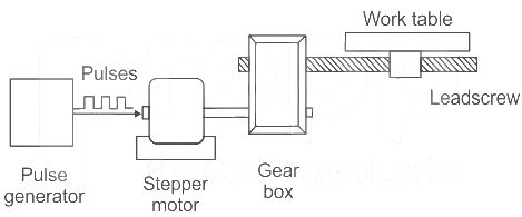
In an open loop, a point-to-point controlled CNC drilling machine, a stepper motor, producing 200 angular steps per revolution, drives the table of a drilling machine by one angular step per pulse generated by a pulse generator (shown in the figure). Each angular step moves the table by one Basic Length Unit (BLU) along X-axis with a lead screw having a pitch of 4 mm. If the frequency of the pulse generator is doubled, the BLU will______
The Basic Length Unit (BLU) is the smallest possible increment of movement the machine can achieve. It's determined by the mechanical design. We are given that each angular step moves the table by one BLU. The angular step is determined by the stepper motor's resolution, not the pulse frequency. Therefore, the BLU is constant and does not depend on the pulse generator's frequency. Doubling the frequency of the pulse generator will only double the speed of the motor and thus the speed of the table movement, but the size of each step (BLU) remains unchanged. So, BLU will remain the same.
Q167GATE 2014NAT
A CNC instruction G91G01X30Y40F100 commands the movement of tool along the path at a feed rate of 100 mm/min (G91-incrememtal format and G01-linear interpolation). The feed rate of the tool (in mm/min) along the X-axis will be ______.
The tool moves a total distance of 50 mm (calculated as 302+402) at a feed rate of 100 mm/min. We need to find the feed rate component along the X-axis. Since the tool covers 50 mm in total while moving 30 mm along the X-axis, the X-axis feed rate is proportionally calculated as: Feed rate along X-axis=50 mm100 mm/min×30 mm=60 mm/min
Q168GATE 2014MCQ
In an open die forging, a circular disc is gradually compressed between two flat platens. The exponential decay of normal stress on the flat face of the disc, from the centre of the disc towards its periphery, indicates that
In open die forging of a circular disc, the exponential decay of normal stress from the center to the periphery indicates how friction behaves. If the disc were frictionless, the normal stress would be uniform. If there was only sticking friction, the stress distribution would be different from exponential decay. The presence of exponential decay suggests that the material is always sliding relative to the platens, meaning the shear stress at the interface is always less than the shear strength required for sticking. This implies that there is no sticking friction anywhere on the flat face of the disc. Therefore, the correct answer is that there is no sticking friction anywhere on the flat face of the disc.
Reaming is a machining operation that uses a reamer to improve the quality of an existing hole, typically after drilling. Its primary purpose is to enlarge the hole slightly to achieve a precise, final dimension, improve the surface finish, and enhance the accuracy of the hole's diameter and roundness. Unlike drilling, which creates the initial hole, reaming removes a very small amount of material to refine the hole's precision and surface finish. Therefore, reaming is fundamentally a finishing process applied to existing holes to meet tight tolerances and quality standards.
Q170GATE 2014NAT
An HSS drill of 20 mm diameter with 5 mm cone height is used to drill a through hole in a steel work-piece of 50 mm thickness. Cutting speed of 10 m/min and feed rate of 0.3 mm/rev are used. The drilling time, in seconds, neglecting the approach and over travel, is _______
The drilling time (Tm) for a through hole is calculated using the formula: Tm=f×NL+AP+OR+h, where L is the workpiece thickness, AP is approach, OR is overtravel, and h is the necessary approach (here, the cone height).
Given: L=50 mm, h=5 mm, AP=0, OR=0, cutting speed Vc=10 m/min, and feed rate f=0.3 mm/rev. Drill diameter D=20 mm.
First, calculate the drill's rotational speed (N) from the cutting speed: Vc=1000π×D×N (since Vc is in m/min and D in mm) N=π×D1000×Vc=π×201000×10=159.154 rpm.
Now, substitute the values into the drilling time formula (note: the original solution uses N=π×D60×Vc and Vc in m/min, so D must be in meters for unit consistency. In the calculation, Vc is multiplied by 1000, making it mm/min, so D remains in mm): N=π×D60×Vc=π×60×2060×10×1000=159.154 rpm.
Therefore, the drilling time is: T=0.3×159.15450+5=47.746255=1.152 minutes.
Converting to seconds: 1.152×60=69.11 seconds.
Q171GATE 2014MCQ
Which one of the following methods is NOT used for producing metal powders?
To produce metal powders, we need to break down bulk metal into fine particles. Atomization involves disintegrating molten metal using high-velocity fluid or centrifugal force, allowing the droplets to solidify into powder. Machining and grinding reduce solid metals into powder through mechanical processes like milling. Electrolysis is an electrochemical method where metal ions deposit onto a cathode and are then collected as powder. Compaction, on the other hand, is a process where already produced metal powder is pressed under high pressure into a solid shape (green compact). Therefore, compaction consolidates existing powder rather than producing it.
Q172GATE 2014MCQ
For a given volume of a riser, if the solidification time of the molten metal in the riser needs to be quadrupled, the surface area of the riser should be made
In casting, the solidification time (Ts) of molten metal in a riser is critical. Chvorinov's rule describes this, stating that Ts is proportional to the square of the ratio of the riser's volume (V) to its surface area (A). This relationship is given by: Ts∝(AV)2
We are given that the riser's volume (V) remains constant, and we need to quadruple the solidification time (Ts). Let the initial state be subscript 1 and the final state be subscript 2. Ts1∝(A1V)2 Ts2∝(A2V)2
We are given Ts2=4×Ts1. Taking the ratio of final to initial solidification times: Ts1Ts2=k(A1V)2k(A2V)2=(A2A1)2
Substituting Ts2=4×Ts1 into the equation: 4=(A2A1)2
Taking the square root of both sides gives: 2=A2A1
Rearranging this to solve for A2: A2=2A1
Therefore, to quadruple the solidification time, the surface area of the riser should be made half.
Q173GATE 2013MCQ
Cylindrical pins of 25+0.010+0.020 mm diameter are electroplated in a shop. Thickness of the plating is 30±2.0 micron. Neglecting gage tolerances, the size of the GO gage in mm to inspect the plated components is
To size a GO gage for a plated component, we need to ensure it checks the maximum material condition of the part. This means the GO gage must correspond to the largest possible diameter of the pin after plating. For a cylindrical pin, the plating adds thickness to the surface. Since the pin has a circular cross-section, plating increases the diameter by twice the plating thickness (one thickness on each side).
Maximum Pin Diameter:
The pin diameter is 25+0.010+0.020 mm.
Maximum Pin Diameter = Nominal Diameter + Upper Tolerance
Maximum Pin Diameter = 25+0.020=25.020 mm.
Maximum Plating Thickness:
The plating thickness is 30±2.0 micron.
Maximum Plating Thickness = Nominal Thickness + Upper Tolerance
Maximum Plating Thickness = 30+2.0=32 micron.
Converting to mm: 32×0.001=0.032 mm.
GO Gage Size Calculation:
For a cylindrical component, the plating adds to the diameter on both sides. Therefore, the total increase in diameter due to plating is 2× Maximum Plating Thickness.
GO Gage Size = Maximum Pin Diameter + (2× Maximum Plating Thickness)
GO Gage Size = 25.020 mm+(2×0.032 mm)
GO Gage Size = 25.020 mm+0.064 mm
GO Gage Size = 25.084 mm.
Q174GATE 2013MCQ
Neglecting the contribution of the feed force towards cutting power, the specific cutting energy in J/mm3 is
The specific cutting energy (u) tells us how much energy is needed to remove a tiny amount (unit volume) of material during machining. We find it by dividing the cutting power (Pc) by the material removal rate (MRR): u=MRRPc.
First, let's gather our given parameters:
Outer Diameter, Do=200 mm
Inner Diameter, Di=80 mm
Feed, f=0.1 mm/rev
Depth of Cut, d=1 mm
Cutting Speed, v=90 m/min
Main Cutting Force, Fc=200 N
Step 1: Calculate Average Diameter (Davg)
For these calculations, we use the average diameter: Davg=2Do+Di=2200 mm+80 mm=140 mm=0.14 m
Step 2: Calculate Cutting Power (Pc)
Cutting power is the product of cutting force and cutting speed. Pc=Fc×v=200 N×90 m/min=18000 N⋅m/min=18000 J/min
Step 3: Calculate Material Removal Rate (MRR)
The MRR can be calculated using the formula MRR=f×d×v. We need to ensure consistent units.
Convert feed and depth of cut to meters: f=0.1 mm/rev=0.0001 m/rev and d=1 mm=0.001 m. MRR=(0.0001 m/rev)×(0.001 m)×(90 m/min)=0.000009 m3/min
Now, convert MRR to mm3/min: MRR=0.000009 m3/min×(109 mm3/1 m3)=9000 mm3/min
Step 4: Calculate Specific Cutting Energy (u)
Finally, we use the calculated cutting power and MRR: u=MRRPc=9000 mm3/min18000 J/min=2 J/mm3
The specific cutting energy is 2 J/mm3.
Q175GATE 2013MCQ
In the 3-2-1 principle of fixture design, 3 refers to the number of
The 3-2-1 principle in fixture design aims to constrain a workpiece's six degrees of freedom (three translational and three rotational) using strategically placed locators. The '3' in the 3-2-1 principle refers to the 3 locators placed on the primary datum face. These three locators establish the foundational positioning and restrict movement along the three axes perpendicular to this face (e.g., X, Y, Z translation). The '2' refers to two locators on the secondary datum face, restricting two rotational movements, and the '1' refers to one locator on the tertiary datum face, restricting the final rotational movement.
Q176GATE 2013MCQ
Assuming approach and over-travel of the cutting tool to be zero, the machining time in min is
This problem asks us to calculate the machining time for a facing operation on a CNC lathe with constant cutting speed.
Given Information:
Outer Diameter (Douter) = 200 mm
Inner Diameter (Dinner) = 80 mm
Feed rate (f) = 0.1 mm/rev
Depth of cut (d) = 1 mm
Constant cutting speed (V) = 90 m/min
Tool approach and over-travel = 0 mm
First, convert all dimensions to consistent units (meters):
Outer Radius (R): R=Douter/2=200 mm/2=100 mm=0.1 m
Inner Radius (r): r=Dinner/2=80 mm/2=40 mm=0.04 m
Feed rate (f): f=0.1 mm/rev=0.0001 m/rev
Cutting speed (V): V=90 m/min
For a facing operation with constant cutting speed, the machining time (Tm) is given by the integral formula: Tm=fVπ(R2−r2)
Note that the depth of cut (1 mm) determines the number of passes (200 mm/1 mm=200 passes, if it were radial, but here depth of cut does not affect the time calculation by this formula).
Substitute the values into the formula: Tm=(0.0001 m/rev)×(90 m/min)π((0.1 m)2−(0.04 m)2) Tm=0.009 m2/rev-minπ(0.01 m2−0.0016 m2) Tm=0.009π(0.0084) min Tm=π×9084 min=π×1514 min Tm≈2.932 min
The calculated machining time is approximately 2.93 minutes.
Q177GATE 2013MCQ
The orthogonal rake angle of the cutting tool in degree is
In orthogonal turning, the main cutting force (Fc) acts tangentially to the workpiece. The friction force (Ffriction) acts along the rake face of the cutting tool. The angle between the rake face direction and the direction of Fc is (90∘−α), where α is the orthogonal rake angle. Since Ffriction acts along the rake face, the angle between Fc and Ffriction is also (90∘−α). The problem states that Fc is perpendicular to Ffriction, meaning the angle between them is 90∘. 90∘−α=90∘
Solving for α: α=90∘−90∘ α=0∘
The orthogonal rake angle is 0∘. Other parameters like diameter, feed, depth of cut, cutting velocity, and the magnitude of Fc are not needed for this calculation.
Q178GATE 2013MCQ
In water jet machining, the water jet is issued through a 0.3 mm diameter orifice at a pressure of 400 MPa. The density of water is 1000 kg/m3. The coefficient of discharge is 1.0. Neglecting all losses during water jet formation through the orifice, the power of the water jet in kW is
We need to calculate the power of the water jet in a Water Jet Machining (WJM) process. We are given the orifice diameter (d), pressure (P), water density (ρ), and coefficient of discharge (Cd). Since losses are neglected, Cd=1.0.
Given Data:
Orifice Diameter, d=0.3 mm=0.3×10⁻³ m
Pressure, P=400 MPa=400×106 Pa
Density of water, ρ=1000 kg/m3
Coefficient of Discharge, Cd=1.0
Step 1: Calculate the Jet Velocity (v)
The kinetic energy per unit volume of the jet is equal to the pressure energy. This gives us the velocity of the water jet. 21ρv2=P
Rearranging for v: v=ρ2P
Substitute the given values: v=1000 kg/m32×(400×106 Pa)=800×103 m/s=800000 m/s≈894.43 m/s
Step 2: Calculate the Orifice Area (A)
The area of the circular orifice is calculated from its diameter. A=4πd2
Substitute the orifice diameter: A=4π(0.3×10⁻³ m)2=4π×0.09×10−6 m2≈7.0686×10⁻⁸ m2
Step 3: Calculate the Volumetric Flow Rate (Q)
The volumetric flow rate is the product of the orifice area, jet velocity, and the coefficient of discharge. Q=Cd×A×v
Substitute the calculated values: Q=1.0×(7.0686×10−8 m2)×(894.43 m/s)≈6.324×10−5 m3/s
Step 4: Calculate the Jet Power (Pjet)
The power of the water jet is the rate at which energy is delivered, which can be found by multiplying the pressure by the volumetric flow rate. Pjet=P×Q
Substitute the pressure and flow rate: Pjet=(400×106 Pa)×(6.324×10⁻⁵ m3/s)≈25296 W
Step 5: Convert Power to Kilowatts (kW)
To express the power in kilowatts, divide by 1000. Pjet≈100025296 kW=25.296 kW
Rounding to one decimal place, the power of the water jet is approximately 25.3 kW.
Q179GATE 2013MCQ
A steel bar 200 mm in diameter is turned at a feed of 0.25 mm/rev with a depth of cut of 4 mm. The rotational speed of the workpiece is 160 rpm. The material removal rate in mm3/s is
To determine the Material Removal Rate (MRR) in turning, we first need to ensure all units are consistent. The rotational speed (N) is given in revolutions per minute (rpm), so we convert it to revolutions per second (rev/s): Nrps=60s/minNrpm=60s/min160rpm=616rev/s=38rev/s
The formula for MRR in turning is given by MRR=π×D×dc×f×Nrps, where D is the diameter, dc is the depth of cut, and f is the feed. Substituting the given values: MRR=π×(200mm)×(4mm)×(0.25mm/rev)×(38rev/s) MRR=π×200×(4×0.25)×38mm3/s MRR=π×200×1×38mm3/s=π×31600mm3/s
Calculating the numerical value, MRR≈3.14159×31600mm3/s≈1675.5mm3/s.
Q180GATE 2013MCQ
Two cutting tools are being compared for a machining operation. The tool life equations are: Carbide tool: VT1.6=3000 HSS tool: VT0.6=200 where V is the cutting speed in m/min and T is the tool life in min. The carbide tool will provide higher tool life if the cutting speed in m/min exceeds
Here's how to figure out when the carbide tool is better:
First, let's express tool life (T) for each tool in terms of cutting speed (V) using the given equations:
For the Carbide tool: VT1.6=3000⟹Tcarbide=(V3000)1.61
For the HSS tool: VT0.6=200⟹THSS=(V200)0.61
We want to find the cutting speed (V) where the carbide tool gives a longer tool life, meaning Tcarbide>THSS: (V3000)1.61>(V200)0.61
To solve for V, we take the natural logarithm of both sides. This allows us to bring the exponents down: 1.61ln(V3000)>0.61ln(V200)
Substitute the decimal values for the exponents (1/1.6=0.625 and 1/0.6≈1.667) and expand the logarithms: 0.625(ln(3000)−ln(V))>1.667(ln(200)−ln(V))
Rearrange the terms to isolate ln(V): 0.625ln(3000)−0.625ln(V)>1.667ln(200)−1.667ln(V) (1.667−0.625)ln(V)>1.667ln(200)−0.625ln(3000) 1.042ln(V)>1.667×5.2983−0.625×8.0064 1.042ln(V)>8.837−5.004 1.042ln(V)>3.833 ln(V)>1.0423.833≈3.678
Finally, to find V, we exponentiate both sides: V>e3.678 V>39.55m/min
Therefore, the carbide tool provides higher tool life when the cutting speed exceeds approximately 39.55 m/min, which is closest to option B.
Want unlimited AI-generated Manufacturing Processes Ii questions?
Sign up free and practice with adaptive difficulty — Easy, Medium, Hard. New questions every session.