If → ' denotes increasing order of intensity, then the meaning of the words [talk → shout → scream] is analogous to [please → ________ → pander]. Which one of the given options is appropriate to fill the blank?
The relationship shown by talk→shout→scream is one of increasing intensity. To solve the analogy, we must find a word that fits the same escalating pattern between please and pander.
To please is to make someone happy. To flatter is to please by using compliments, often insincerely, for personal gain. This is a more intense action than simply pleasing. To pander is to gratify or indulge someone's desires, often in a negative or immoral way, which is an extreme form of pleasing. Thus, the sequence please→flatter→pander shows a clear and logical increase in the intensity and often the insincerity of the act. The other options are semantically unrelated.
Q2GATE 2024MCQ1MGeneral Aptitude
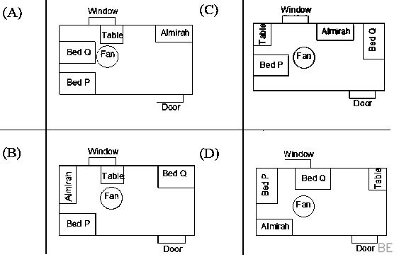
P and Q have been allotted a hostel room with two beds, a study table, and an almirah. P is an avid bird-watcher and wants to sit at the table and watch birds outside the window. Q does not mind that as long as his bed is close to the ceiling fan. Which one of the following arrangements suits them the most?
To solve this, we must satisfy two conditions simultaneously. First, P wants the table near the window for bird-watching. This eliminates options C and D, where the table is on the opposite wall from the window. We are now left with options A and B, both of which place the table by the window.
The second condition is that Q's bed must be close to the ceiling fan. In arrangement A, Bed Q is directly adjacent to the fan. In arrangement B, Bed Q is positioned far from the fan, on the other side of the room. Therefore, only arrangement A satisfies both P's and Q's preferences.
Q3GATE 2024MCQ1MGeneral Aptitude
The decimal number system uses the characters 0,1,2,….,8,9 , and the octal number system uses the characters 0,1,2,…,6,7 . For example, the decimal number 12(=1×101+2×100) is expressed as 14(=1×81+4×80) in the octal number system. The decimal number 108 in the octal number system is
To solve this, we can check the options by converting them from octal (base-8) to their decimal (base-10) equivalent. The correct option will be the one that equals 108.
Let's test the octal number 154. In base-8, the place values from right to left are powers of 8 (80, 81, 82, etc.). We can expand 1548 as follows: (1×82)+(5×81)+(4×80) =(1×64)+(5×8)+(4×1) =64+40+4=108
Since the calculation results in 108, we've confirmed that 154 is the octal representation of the decimal number 108.
Q4GATE 2024MCQ1MGeneral Aptitude
A shopkeeper buys shirts from a producer and sells them at 20% profit. A customer has to pay ₹ 3,186.00 including 18% taxes, per shirt. At what price did the shopkeeper buy each shirt from the producer?
Let's denote the price the shopkeeper paid as C. The shopkeeper adds a 20% profit, so their selling price is the original cost multiplied by 1.20. Next, an 18% tax is added to this selling price, which is equivalent to multiplying it by 1.18. This gives us the final price the customer pays.
We can express this as a single equation: C×1.20×1.18=3,186
To find the original cost, C, we simply rearrange and solve: C=1.20×1.183,186=1.4163,186 C=₹ 2,250.00
Q5GATE 2024MCQ1MGeneral Aptitude
If, for non-zero real variables x,y and real parameter a>1 , x:y=(a+1):(a−1), then, the ratio (x2−y2):(x2+y2) is
We begin with the given proportion, which can be written as the equation yx=a−1a+1.
To find the desired ratio, it's useful to first manipulate the expression by dividing the numerator and denominator by y2: x2+y2x2−y2=(yx)2+1(yx)2−1
Now, substitute the known value of yx: (a−1a+1)2+1(a−1a+1)2−1=(a+1)2+(a−1)2(a+1)2−(a−1)2
Expanding the squares gives the numerator (a2+2a+1)−(a2−2a+1)=4a and the denominator (a2+2a+1)+(a2−2a+1)=2a2+2.
Thus, the expression simplifies to 2a2+24a=a2+12a.
Q6GATE 2024MCQ2MGeneral Aptitude
In the given text, the blanks are numbered (i)-(iv). Select the best match for all the blanks. Following a row (i) the shopkeeper (ii) the price of a frying pan, the cook stood (iii) a row to withdraw cash (iv) the ATM booth.
This sentence uses the word "row" in two different ways, which guides the choice of prepositions. The first "row" means an argument; the correct idiom is to have a row *with* someone (i) *over* a topic (ii). This narrows the options to A and C. The second "row" means a line or queue; a person stands *in* a row (iii). This eliminates option A. Finally, *at* the ATM booth (iv) is the correct preposition to denote the location. Thus, the sequence "with, over, in, at" creates a grammatically and idiomatically sound sentence.
Q7GATE 2024MCQ2MGeneral Aptitude
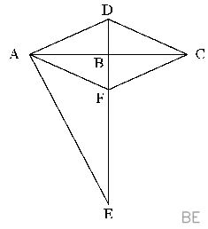
In the following figure,
CD∠DAB=5cm,BE=10cm,AE=12cm=∠DCB and ∠DAE=∠DBC=90∘
Points AFCD create a rhombus. The length of BF (in cm ) is
Since AFCD is a rhombus, its sides are equal, so we have DA=CD=FC=5cm. In the right-angled triangle △DAE, we use the Pythagorean theorem to find the length of the hypotenuse DE: DE=DA2+AE2=52+122=25+144=169=13cm.
From the figure, points D, B, and E are collinear. Thus, we can find the length of DB by subtracting BE from DE: DB=DE−BE=13−10=3cm. Now consider the right-angled triangle △DBC. We can find the length of BC using the Pythagorean theorem again: BC=CD2−DB2=52−32=25−9=16=4cm.
Since F lies on the same line as D and B, and ∠DBC=90∘, it follows that △FBC is also a right-angled triangle at B. Using the Pythagorean theorem for △FBC, we solve for BF: BF=FC2−BC2=52−42=25−16=9=3cm.
Q8GATE 2024MCQ2MGeneral Aptitude
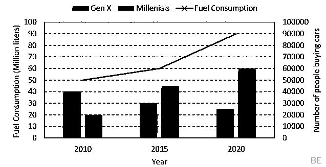
The chart below shows the data of the number of cars bought by Millennials and Gen X people in a country from the year 2010 to 2020 as well as the yearly fuel consumption of the country (in Million liters). Considering the data presented in the chart, which one of the following options is true?
To evaluate the correct option, let's analyze the changes in car buyers from 2010 to 2015 as described in option C.
From the chart, the number of Millennial car buyers increased from approximately 20,000 in 2010 to 45,000 in 2015. The total increase is 45,000−20,000=25,000.
In the same period, the number of Gen X car buyers decreased from approximately 40,000 in 2010 to 30,000 in 2015. The total decrease is 40,000−30,000=10,000.
Option C states that the increase for Millennials is more than the decrease for Gen X. Comparing our calculated values, we see that 25,000>10,000. This confirms the statement is true.
Q9GATE 2024MCQ2MGeneral Aptitude
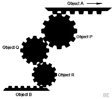
The assembly shown below has three teethed circular objects (Pinions) and two teethed flat objects (Racks), which are perfectly mating with each other. Pinions can only rotate clockwise or anti-clockwise staying at its own center. Racks can translate towards the left (\leftarrow)ortheright(→ ) direction. If the object A (Rack) is translating towards the right (\rightarrow$ ) direction, the correct statement among the following is
The movement of Rack A to the right (\rightarrow)causesPinionPtorotateclockwise.SincePinionPandPinionQareexternallymeshed,theclockwiserotationofPcausesQtorotateanti−clockwise.Consequently,PinionQ′santi−clockwiserotationcausesthemeshedPinionRtorotateclockwise.PinionRisengagedwiththetopsurfaceofRackB.AsPinionRrotatesclockwise,itsbottompoint∈contactwithRackBmovestotheleft,pushingRackB∈theleft(←) direction. Thus, Object B translates towards the left.
Q10GATE 2024MCQ2MGeneral Aptitude
A surveyor has to measure the horizontal distance from her position to a distant reference point C. Using her position as the center, a 200m horizontal line segment is drawn with the two endpoints A and B . Points A,B and C are not collinear. Each of the angles ∠CAB and ∠CBA are measured as 87.8∘ . The distance (in m ) of the reference point C from her position is nearest to
Let's visualize the setup. The surveyor's position is the center of the 200m line segment AB. Let's call this position M. This means the distance from her to endpoint A is AM=100m.
Because the angles ∠CAB and ∠CBA are equal, the triangle △ABC is isosceles. The line from vertex C to the midpoint M of the base is therefore an altitude, creating a right-angled triangle, △AMC.
We want to find the distance MC. In △AMC, we know the angle ∠CAM=87.8∘ and the adjacent side AM=100m. The side we're looking for, MC, is opposite the angle. Using the tangent ratio: tan(87.8∘)=adjacentopposite=100MC
Solving for the distance MC, we get: MC=100×tan(87.8∘)≈2603m
EE55 questions
Q11GATE 2024MCQ1MEngineering Mathematics
Which one of the following matrices has an inverse?
A key principle in linear algebra is that a matrix has an inverse if and only if its determinant is non-zero. A quick way to identify a matrix with a zero determinant is to spot linearly dependent rows or columns.
In matrices A, B, and D, one row is a direct multiple of another:
In A: Row 3 is 0.5 times Row 1.
In B: Row 2 is 2 times Row 1.
In D: Row 3 is 3 times Row 1.
This linear dependence guarantees that their determinants are all 0, so they cannot be inverted. Matrix C does not have linearly dependent rows, meaning its determinant is non-zero, and thus it has an inverse.
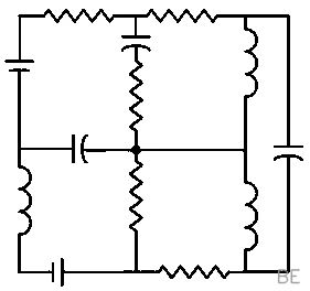
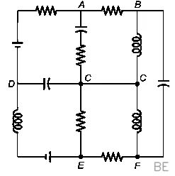
In an electrical circuit, a junction is a point where the leads of three or more components are connected. We can find the total number of junctions by systematically scanning the diagram for these connection points.
There are two junctions where four components meet:
The explicit dot in the very center of the circuit.
The entire bottom wire, which acts as a single common node for four components.
Additionally, there are four junctions where three components meet:
The T-intersection at the top left.
The T-intersection at the top right.
The T-intersection directly above the center point.
The T-intersection directly below the center point.
In total, there are 2+4=6 junctions in the circuit.
Q13GATE 2024MCQ1MElectric Circuits
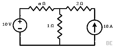
All the elements in the circuit are ideal. The power delivered by the 10V source in watts is
To determine the power delivered by the 10V source, we must find the current flowing out of its positive terminal. We can solve this using the superposition theorem by considering each source independently.
First, let's find the current due to the 10V source alone by replacing the 10A current source with an open circuit. The circuit becomes a simple series loop, and the current I1 is I1=(α+1)Ω10V. This current flows clockwise.
Next, we find the current due to the 10A source alone by replacing the 10V source with a short circuit. The 10A current flows towards the central junction, where it splits. Using the current divider rule, the current I2 flowing through the branch with the αΩ resistor is I2=10A⋅(α+1)Ω1Ω=α+110A. This current flows counter-clockwise through the left loop.
The total current I from the 10V source is the sum of these two components. Defining clockwise as the positive direction, we get: I=I1−I2=α+110−α+110=0A.
Since the total current flowing from the 10V source is zero, the power delivered by it is P=V⋅I=10V×0A=0W.
Q14GATE 2024MCQ1MElectric Circuits
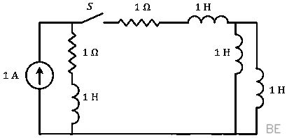
The circuit shown in the figure with the switch S open, is in steady state. After the switch S is closed, the time constant of the circuit in seconds is
To determine the time constant of the circuit after the switch closes, we must find the equivalent resistance (Req) and equivalent inductance (Leq) of the network. The time constant τ is then given by their ratio.
First, let's calculate the total equivalent inductance. The two 1 H inductors on the far right are in parallel, giving an equivalent of (1∥1)=0.5 H. This combination is effectively in series with the other two 1 H inductors in the circuit. Therefore, the total inductance is Leq=1 H+1 H+0.5 H=2.5 H.
Next, we find the total equivalent resistance. The two 1Ω resistors are effectively in series in the path of the current, so the total resistance is Req=1Ω+1Ω=2Ω.
Finally, we calculate the time constant using the formula τ=ReqLeq. τ=2Ω2.5 H=1.25 s.
Q15GATE 2024MCQ1MSignals and Systems
Suppose signal y(t) is obtained by the time-reversal of signal x(t) , i.e., y(t)=x(−t) , −∞lttlt∞ . Which one of the following options is always true for the convolution of x(t) and y(t) ?
Let the convolution of x(t) and y(t) be denoted by z(t). Given that y(t)=x(−t), we can express the convolution as z(t)=x(t)∗x(−t).
To check for symmetry, we evaluate the signal at time −t: z(−t)=x(−t)∗x(−(−t))=x(−t)∗x(t)
Convolution is a commutative operation, meaning the order of the signals does not change the result. Therefore, we can write: z(−t)=x(t)∗x(−t)
This expression is identical to our original definition of z(t). Since z(−t)=z(t), the resulting signal is, by definition, always an even signal.
Q16GATE 2024MCQ1MSignals and Systems
If u(t) is the unit step function, then the region of convergence (ROC) of the Laplace transform of the signal x(t)=et2[u(t−1)−u(t−10)] is
The signal x(t) is a product of the function et2 and the term [u(t−1)−u(t−10)]. This second term is a rectangular pulse that is non-zero only for the finite time interval 1≤t<10. This means x(t) itself is a finite-duration signal.
The Laplace transform is defined by an integral, X(s)=∫t1t2x(t)e−stdt. For any finite-duration signal, the limits of this integral are finite. In this case, the integral is ∫110et2e−stdt. Since we are integrating a function over a finite interval, the result will converge for any finite value of s. Therefore, the region of convergence is the entire s-plane.
Q17GATE 2024MCQ1MElectrical Machines
A three phase, 50Hz,6 pole induction motor runs at 960rpm . The stator copper loss, core loss, and the rotational loss of the motor can be neglected. the percentage efficiency of the motor is
First, we determine the synchronous speed (Ns) of the motor's magnetic field. This is given by the formula Ns=P120f, where f is the frequency and P is the number of poles. Ns=6120×50=1000 rpm
Next, we calculate the slip (s), which is the fractional difference between the synchronous speed and the actual rotor speed (Nr). s=NsNs−Nr=10001000−960=0.04
The problem states that all major losses (stator, core, rotational) are neglected. In this simplified scenario, the efficiency (η) is determined by the relationship between the mechanical output power and the electrical input power to the rotor, which is given by η=1−s.
Plugging in our value for slip, we find the efficiency: η=1−0.04=0.96, or 96%.
Q18GATE 2024MCQ1MElectrical Machines
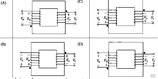
Which one of the following options represents possible voltage polarities in a single phase two winding transformer? Here, Vp is the applied primary voltage, Ep is the induced primary voltage, Vs is the open circuit secondary voltage, and Es is the induced secondary voltage.
Here is a concise explanation of the voltage polarities in a transformer:
**Primary Side:** In an ideal transformer, the applied primary voltage (Vp) must be equal and opposite to the back-EMF it creates. However, the induced voltage (Ep) shown in circuit diagrams is conventionally defined as being equal to the applied voltage, so Vp=Ep. This means their polarities are the same. This condition eliminates options (C) and (D), where Vp and Ep have opposite polarities.
**Secondary Side:** For an open-circuited secondary winding, no current flows. Therefore, the terminal voltage (Vs) is exactly equal to the induced electromotive force (Es). Their polarities must be identical (Vs=Es). Both remaining options, (A) and (B), satisfy this.
**Dot Convention:** The dots indicate terminals that are in phase. The induced voltage at the dotted primary terminal (Ep) has the same polarity as the induced voltage at the dotted secondary terminal (Es). In option (B), the dotted primary terminal (bottom) is positive for Ep, and the dotted secondary terminal (top) is also positive for Es. This is consistent. In option (A), the dotted primary is negative while the dotted secondary is positive, which violates the dot convention.
Q19GATE 2024MCQ1MPower Systems
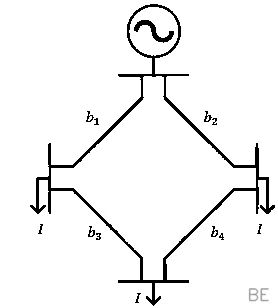
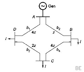
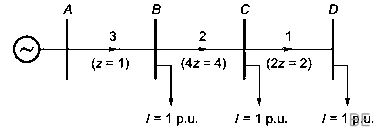
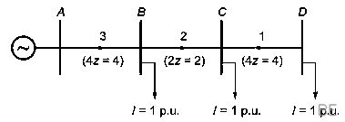
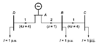
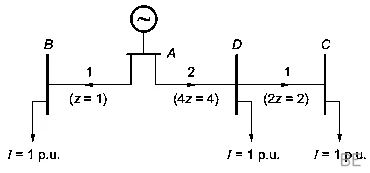
The figure shows the single line diagram of a 4-bus power network, Branches b1,b2 , b3 and b4 have impedances 4z,z,2z and 4z per-unit (pu), respectively, where z=r+jx , with r>0 and x>0 . The current drawn from each load bus (marked as arrows) is equal to I pu, where I=0 . If the network is to operate with minimum loss, the branch that should be opened is
To find the configuration with minimum loss, we must compare the total power loss for each case where one branch is opened. When a branch is opened, the ring network becomes a radial one. The total power loss is proportional to ∑Ibranch2Zbranch, so we can compare a simplified loss factor for each scenario using the given impedance coefficients and assuming unit load currents (I=1).
**Open b1**: All three loads are fed in series through path b2→b4→b3. The currents in the branches are 3I, 2I, and I respectively. The loss factor is 32(1)+22(4)+12(2)=27.
**Open b2**: Similar to the first case, the path is now b1→b3→b4. The loss factor is 32(4)+22(2)+12(4)=48.
**Open b3**: The network splits into two separate feeders. Path b1 supplies one load (I), while path b2→b4 supplies two loads (current is 2I in b2 and I in b4). The total loss factor is 12(4)+22(1)+12(4)=12.
Comparing the calculated loss factors (27, 48, and 12), opening branch b3 yields the minimum value. This configuration is most efficient because it avoids forcing the largest currents through high-impedance lines.
Q20GATE 2024MCQ1MControl Systems
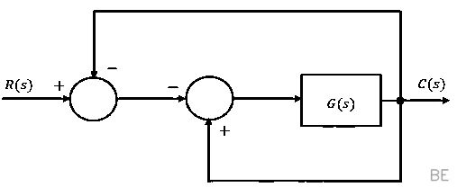
For the block-diagram shown in the figure, the transfer function R(s)C(s) is
To find the transfer function R(s)C(s), let's write out the algebraic relationships for the signals in the diagram.
First, let's define the signal entering the block G(s) as E(s). The output is then simply C(s)=G(s)E(s).
Next, we express E(s) in terms of the input R(s) and output C(s). The first summer calculates R(s)−C(s). This result enters the second summer with a negative sign, while C(s) enters with a positive sign. Thus, E(s)=−(R(s)−C(s))+C(s), which simplifies to E(s)=−R(s)+2C(s).
Now, substitute this expression for E(s) back into our output equation: C(s)=G(s)[−R(s)+2C(s)]=−G(s)R(s)+2G(s)C(s).
Finally, we rearrange the equation to solve for the ratio R(s)C(s): C(s)−2G(s)C(s)=−G(s)R(s) C(s)[1−2G(s)]=−G(s)R(s) R(s)C(s)=1−2G(s)−G(s)
Q21GATE 2024MCQ1MControl Systems
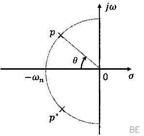
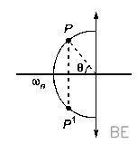
Consider the standard second-order system of the form s2+2ξωns+ωn2ωn2 with the poles p and p⋆ having negative real parts. The pole locations are also shown in the figure. Now consider two such second-order systems as defined below : System 1 : ωn=3rad/sec and θ=60∘ System 2 : ωn=1rad/sec and θ=70∘ Which one of the following statements is correct?
The settling time (ts) is inversely proportional to the real part of the system's poles. For a standard second-order system, the 2% settling time is given by the formula ts≈ξωn4. The s-plane diagram shows that the damping ratio ξ is related to the pole angle θ by ξ=cosθ.
For System 1, with ωn1=3 and θ1=60∘, the damping ratio is ξ1=cos(60∘)=0.5. The settling time is ts1=ξ1ωn14=0.5×34=38≈2.67 seconds.
For System 2, with ωn2=1 and θ2=70∘, the damping ratio is ξ2=cos(70∘). The settling time is ts2=ξ2ωn24=cos(70∘)×14≈11.69 seconds.
Comparing these results, it's clear that ts2>ts1.
Q22GATE 2024MCQ1MControl Systems
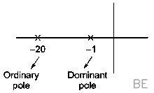
Consider the cascaded system as shown in the figure. Neglecting the faster component of the trasient response, which one of the following options is a first-order pole-only approximation such that the steady-state values of the unit step responses of the original and the approximated system are same?
To find the simplified model, we first determine the complete transfer function of the cascaded system by multiplying the two blocks: G(s)=s+11×s+20s+40=(s+1)(s+20)s+40
This second-order system has poles at s=−1 and s=−20. The pole at s=−1 is the dominant pole because it is much closer to the imaginary axis, creating a slower response. The pole at s=−20 corresponds to a faster transient component, which we are told to neglect.
Our first-order approximation will therefore retain the dominant pole, giving it the form Gapprox(s)=s+1K. To ensure the steady-state values match, we equate the DC gains (the value when s=0) of the original and approximated systems. The DC gain of the original system is G(0)=(0+1)(0+20)0+40=2. The DC gain of the approximation is Gapprox(0)=K. Thus, we set K=2, yielding the approximation s+12.
Q23GATE 2024MCQ1MElectrical and Electronic Measurements
The table lists two instrument transformers and their features:
Instrument Transformers(X) Current Transformer(CT)(Y) Potential Transformer(PT)Features(P) Primary is connected in parallel to the grid(Q) Open circuited secondary is not desirable(R) Primary current is the line current(S) Secondary burden affects the primary current
A Current Transformer (CT) is connected in series with the power line, so its primary winding carries the full line current (R). A critical safety precaution for a CT is that its secondary must never be open-circuited, as this would induce dangerously high voltages (Q). Therefore, X (CT) matches with Q and R.
A Potential Transformer (PT) is used to measure voltage and is connected in parallel with the grid (P). Like a standard transformer, the primary current it draws from the line is dependent on the impedance of the secondary load, also known as the burden (S). Thus, Y (PT) matches with P and S.
Q24GATE 2024MCQ1MDigital Electronics
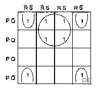
Simplified form of the Boolean function: F(P,Q,R,S)=PˉQˉ+PˉQS+PQˉRˉSˉ+PQˉRSˉ is
To simplify the Boolean function, we can start by looking for common factors. Notice the last two terms, PQˉRˉSˉ and PQˉRSˉ, share PQˉSˉ. Factoring this out gives us PQˉSˉ(Rˉ+R), which simplifies to PQˉSˉ since Rˉ+R=1.
The expression is now F=PˉQˉ+PˉQS+PQˉSˉ. To find more simplifications, we can strategically expand the term PˉQˉ by multiplying it by (S+Sˉ), which results in PˉQˉS+PˉQˉSˉ.
Now substitute this back and rearrange the function to group common variables: F=(PˉQˉS+PˉQS)+(PˉQˉSˉ+PQˉSˉ).
Factoring the first group yields PˉS(Qˉ+Q)=PˉS. Factoring the second group yields QˉSˉ(Pˉ+P)=QˉSˉ.
Combining these two results gives the final simplified expression: PˉS+QˉSˉ.
Q25GATE 2024MCQ1MDigital Electronics
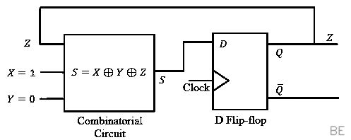
In the circuit, the present value of Z is 1 . Neglecting the delay in the combinatorial circuit, the values of S and Z , respectively, after the application of the clock will be
First, let's determine the value of S which acts as the input to the D flip-flop. Using the given present state values, X=1,Y=0, and Z=1, we can calculate the initial value of S: S=X⊕Y⊕Z=1⊕0⊕1=0.
When the clock pulse arrives, the D flip-flop captures this value of S=0. The output of the flip-flop, Z, will then update to become 0.
This new value, Z=0, is fed back as an input to the combinatorial circuit. Since the delay is negligible, S is immediately recalculated with this new input: S=X⊕Y⊕Z=1⊕0⊕0=1.
Therefore, after the clock application, the circuit settles to the new state where S=1 and Z=0.
Q26GATE 2024MCQ1MDigital Electronics
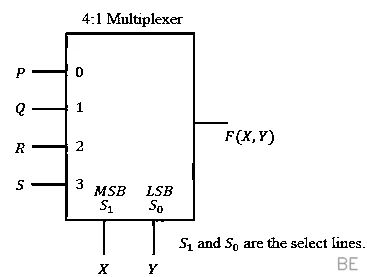
To obtain the Boolean function F(X,Y)=XYˉ+Xˉ , the inputs PQRS in the figure should be
The output of a 4:1 multiplexer with select lines S1=X and S0=Y is given by the equation F=PXˉYˉ+QXˉY+RXYˉ+SXY. We need to match this to the desired function F(X,Y)=XYˉ+Xˉ by determining the values for inputs P,Q,R,S. An implementation table helps map the select line combinations to the required inputs.
We evaluate the target function for each combination of X and Y:
When XY=00, F(0,0)=0⋅0ˉ+0ˉ=1. The MUX selects input P, so P=1.
When XY=01, F(0,1)=0⋅1ˉ+0ˉ=1. The MUX selects input Q, so Q=1.
When XY=10, F(1,0)=1⋅0ˉ+1ˉ=1. The MUX selects input R, so R=1.
When XY=11, F(1,1)=1⋅1ˉ+1ˉ=0. The MUX selects input S, so S=0.
Therefore, the required inputs are PQRS=1110.
Q27GATE 2024MCQ1MPower Electronics
If the following switching devices have similar power ratings, which one of them is the fastest?
The switching speed of a power device is determined by its turn-on and turn-off times. The Power MOSFET is a unipolar or majority carrier device, meaning its operation depends only on one type of charge carrier (electrons or holes). In contrast, SCRs, GTOs, and IGBTs are all bipolar devices, involving both majority and minority carriers. During turn-off, these bipolar devices experience a significant delay due to the time required to remove stored minority carriers from the base/drift regions. This "storage time" is absent in a MOSFET, allowing it to switch much faster. The MOSFET's speed is primarily limited only by the time needed to charge and discharge its internal gate capacitances (Cgs, Cgd).
Q28GATE 2024MCQ1MPower Electronics
A single-phase triac based AC voltage controller feeds a series RL load. The input AC supply is 230V,50Hz . The values of R and L are 10Ω and 18.37mH , respectively. The minimum triggering angle of the triac to obtain controllable output voltage is
For an AC voltage controller with a series RL load, the output is controllable only when the triggering angle, α, is greater than the load's phase angle, θ. This condition (α>θ) ensures the triac conducts for a controllable duration. The load phase angle is determined by the circuit's resistance and inductive reactance.
We calculate this angle using the formula θ=tan−1(RωL), where the angular frequency is ω=2πf.
Substituting the given values: θ=tan−1(10Ω2π(50 Hz)(18.37×10⁻³ H))
This calculation gives θ≈29.99∘. Therefore, the minimum triggering angle required for controllable output is approximately 30∘.
Q29GATE 2024MSQ1MEngineering Mathematics
Let X be a discrete random variable that is uniformly distributed over the set {−10,−9,…,0,…,9,10} . Which of the following random variables is/are uniformly distributed?
The random variable X can take on 21 distinct integer values, each with a probability of 1/21. For a new random variable created by a function of X to also be uniformly distributed, the function must be a one-to-one mapping over X's domain. This means that each of the 21 values of X must produce a unique output value.
Let's examine the options based on this principle.
A. X2 is not uniform because multiple inputs give the same output. For example, X=2 and X=−2 both result in X2=4. Thus, P(X2=4)=2/21, while P(X2=0)=1/21.
C. (X−5)2 is also not uniform for the same reason. Values of X that are symmetric around 5, like X=4 and X=6, both produce (X−5)2=1.
B. X3 is a strictly increasing function, so every distinct value of X maps to a distinct value of X3. This creates 21 unique outcomes, each with probability 1/21.
D. (X+10)2 is also uniform. First, the variable Y=X+10 takes on the unique values {0,1,2,…,20}. Squaring these distinct non-negative numbers produces 21 unique results, so each has a probability of 1/21.
Q30GATE 2024MCQ1MEngineering Mathematics
Which of the following complex functions is/are analytic on the complex plane?
To determine if a function is analytic across the entire complex plane, we can test if it satisfies the Cauchy-Riemann equations everywhere. Let's examine the function f(z)=z2−z.
First, we express f(z) in terms of its real part, u(x,y), and imaginary part, v(x,y), by substituting z=x+iy: f(z)=(x+iy)2−(x+iy)=(x2−y2−x)+i(2xy−y)
So, we have u=x2−y2−x and v=2xy−y.
Next, we calculate the partial derivatives: ux=2x−1, uy=−2y vx=2y, vy=2x−1
Finally, we check the Cauchy-Riemann equations: ux=vy and uy=−vx. We see that ux=2x−1=vy and uy=−2y=−vx. Since these equations hold for all values of x and y, the function is analytic on the entire complex plane.
Q31GATE 2024NAT1MEngineering Mathematics
Consider the complex function f(z)=cosz+ez2 . The coefficient of z5 in the Taylor series expansion of f(z) about the origin is _____ (rounded off to 1 decimal place).
To find the coefficient of a specific term in a Taylor series, we can analyze the properties of the function itself. The given function is f(z)=cosz+ez2.
Notice that both cosz and ez2 are even functions, meaning their value is unchanged when z is replaced by −z. The Taylor series of an even function about the origin contains only even powers of z.
The series for cosz is 1−2!z2+4!z4−….
The series for ez2 is 1+z2+2!z4+3!z6+….
Since f(z) is the sum of two series that contain only even powers, its own series expansion will consist solely of even-powered terms. Therefore, the coefficient of any odd-powered term, such as z5, must be 0.
First, we must calculate the matrix A by squaring the given matrix:
A=(1324)(1324)=(7151022)
A key property of any square matrix is that the sum of its eigenvalues is equal to its trace. The trace is simply the sum of the elements on the main diagonal.
For our calculated matrix A, the trace is the sum of its diagonal entries, 7 and 22.
Therefore, the sum of the eigenvalues is Trace(A)=7+22=29.
Q33GATE 2024NAT1MSignals and Systems
Let X(ω) be the Fourier transform of the signal, x(t)=e−t4cost,−∞<t<∞ . The value of the derivative of X(ω) at ω=0 at is _____ (rounded off to 1 decimal place)
We can solve this by using the differentiation in frequency property of the Fourier transform, which states that if x(t)↔X(ω), then tx(t)↔jdωdX(ω).
Rearranging this property, we see that the derivative we are looking for, dωdX(ω), is the Fourier transform of the time-domain signal jtx(t).
To find the value of any Fourier transform at ω=0, we simply calculate the total area under its corresponding time-domain signal. Thus, we need to evaluate the integral ∫−∞∞jtx(t)dt.
Let's analyze the function inside the integral. The given signal x(t)=e−t4cost is an even function, as it is a product of two even functions. The function we are integrating is jtx(t), which is an odd function because it's the product of an odd function (t) and an even function (x(t)). The integral of any odd function over a symmetric interval from −∞ to ∞ is always zero.
Q34GATE 2024NAT1MPower Systems
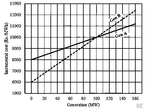
The incremental cost curves of two generators (Gen A and Gen B) in a plant supplying a common load are shown in the figure. If the incremental cost of supplying the common load is Rs. 7400 per MWh, then the common load in MW is ____ (rounded off to the nearest integer).
For the most economical operation, all generators should operate at the same incremental cost, λ, which is given as 7400 Rs/MWh.
From the graph, we can find the cost equation for Generator A: ICA=20PGA+8000. Setting this to λ gives 20PGA+8000=7400, which results in a physically impossible negative power output (PGA=−30 MW). This indicates that Generator A's minimum cost (8000 Rs/MWh) is above the operating cost, so it must be shut down (PGA=0).
Therefore, Generator B must supply the entire load. Its cost equation is ICB=40PGB+6000.
Setting its cost to λ yields 40PGB+6000=7400.
Solving for PGB gives an output of 35 MW. The total load is PGA+PGB=0+35=35 MW.
Q35GATE 2024NAT1MPower Electronics
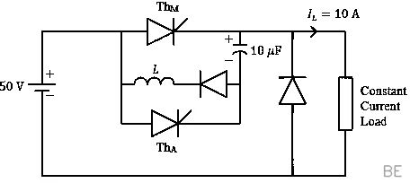
A forced commutated thyristorized step-down chopper is shown in the figure. Neglect the ON-state drop across the power devices. Assume that the capacitor is initially charged to 50V with the polarity shown in the figure. The load current (IL) can be assumed to be constant at 10A . Initially, ThM is ON and ThA is OFF. The turn-off time available to ThM in microseconds, when ThA is triggered, is _____ (rounded off to the nearest integer).
To turn off the main thyristor, ThM, the auxiliary thyristor, ThA, is triggered. This connects the capacitor, initially charged to 50 V, in parallel with ThM, applying a reverse voltage and forcing it to commutate. The constant load current, IL=10 A, is now diverted through the capacitor, causing it to discharge.
The turn-off time available to ThM is the duration for which it remains reverse-biased. This period lasts until the capacitor voltage drops from its initial 50 V down to zero. We can calculate this time using the capacitor's voltage-current relationship for a constant discharging current:
toff=ILC⋅VC=10 A(10×10−6 F)⋅(50 V)
toff=50×10−6 s=50μs
Q36GATE 2024MCQ2MEngineering Mathematics
Consider a vector uˉ=2x^+y^+2z^ , where x^,y^,z^ represent unit vector along the coordinate axes x,y,z respectively. The directional derivative of the function f(x,y,z)=2ln(xy)+ln(yz)+3ln(xz) at the point (x,y,z)=(1,1,1) in the direction of uˉ is
The directional derivative is the dot product of the gradient of the function (∇f) and the unit vector for the given direction (u^).
First, let's find the gradient of f. It's helpful to simplify the function using logarithm properties: f(x,y,z)=2(lnx+lny)+(lny+lnz)+3(lnx+lnz)=5lnx+3lny+4lnz.
The gradient is ∇f=x5x^+y3y^+z4z^. At the point (1,1,1), this becomes ∇f∣(1,1,1)=5x^+3y^+4z^.
Next, we find the unit vector for the direction uˉ=2x^+y^+2z^. The magnitude is ∣uˉ∣=22+12+22=9=3. So, the unit vector is u^=∣uˉ∣uˉ=31(2x^+y^+2z^).
Finally, we compute the dot product of the gradient and the unit vector: (5x^+3y^+4z^)⋅31(2x^+y^+2z^)=31(5⋅2+3⋅1+4⋅2)=31(10+3+8)=321=7.
Q37GATE 2024MCQ2MSignals and Systems
The input x(t) and the output y(t) of a system are related as y(t)=e−t∫−∞teτx(τ)dτ,−∞<t<∞ The system is
The system is linear because integration and scaling are linear operations, and the system is composed of only these.
To check for time-invariance, we must verify if a shifted input x(t−t0) produces a correspondingly shifted output, y(t−t0). Let's find the output, which we'll call ynew(t), for the shifted input x(t−t0): ynew(t)=e−t∫−∞teτx(τ−t0)dτ
Now, let's change the variable of integration to k=τ−t0. This means τ=k+t0, and the upper limit of integration becomes t−t0. ynew(t)=e−t∫−∞t−t0ek+t0x(k)dk
Simplifying by factoring out the constant et0 gives: ynew(t)=e−tet0∫−∞t−t0ekx(k)dk=e−(t−t0)∫−∞t−t0ekx(k)dk
This final expression is precisely the original system equation for y(t) with every t replaced by (t−t0). Thus, ynew(t)=y(t−t0), and the system is time-invariant.
Q38GATE 2024MCQ2MSignals and Systems
Consider the discrete-time system T1 and T2 defined as follows:
To test for Bounded-Input, Bounded-Output (BIBO) stability, we check if a bounded input can produce an unbounded output.
First, consider system T1, which is a discrete-time accumulator. If we use a simple bounded input like the unit step function, x[n]=u[n], the output becomes {T1x}[n]=∑k=0nu[k]=n+1. As n increases, this output grows without limit. Therefore, T1 is not BIBO stable.
Next, consider system T2. Let's assume a general bounded input, where ∣x[n]∣≤M for some finite constant M. The magnitude of the output is bounded by ∣{T2x}[n]∣≤∑k=0n∣(21)kx[k]∣≤M∑k=0n(21)k. This sum is a geometric series that converges to 2 as n→∞. The output is therefore always bounded by 2M, proving that T2 is BIBO stable.
Q39GATE 2024MCQ2MSignals and Systems
If the Z-transform of a finite-duration discrete-time signal x[n] is X(z) , then the Z -transform of the signal y[n]=x[2n] is
The process of finding the Z-transform of y[n]=x[2n], a downsampled signal, begins with the Z-transform definition: Y(z)=∑n=−∞∞y[n]z−n=∑n=−∞∞x[2n]z−n
To relate this to X(z), which is a sum over all samples of x[k], we can change the summation index to k=2n. The sum is now over all even integers k, and the term z−n becomes z−k/2: Y(z)=∑k is evenx[k](z1/2)−k
A useful technique to convert a sum over even indices to a sum over all indices is to use the expression 21+(−1)k, which is 1 for even k and 0 for odd k. Applying this "filter" yields: Y(z)=∑k=−∞∞x[k](z1/2)−k(21+(−1)k)
We can then separate this into two distinct sums: Y(z)=21[∑k=−∞∞x[k](z1/2)−k+∑k=−∞∞x[k](−z1/2)−k]
By recognizing the definition of the Z-transform, X(v)=∑kx[k]v−k, we can identify the two resulting terms, giving the final expression.
Q40GATE 2024MCQ2MElectrical Machines
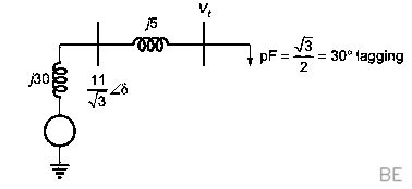
A 3-phase. 11kV.10 MVA synchronous generator is connected to an inductive load of power factor (3/2) via a lossless line with a per-phase inductive reactance of 5Ω . The per-phase synchronous reactance of the generator is 30Ω with negligible armature resistance. If the generator is producing the rated current at the rated voltage, then the power factor at the terminal of the generator is
First, let's establish the per-phase rated values. The generator's terminal voltage is Vt=311 kV≈6351 V, and the rated current is I=3×11 kV10 MVA=524.86 A. The inductive load has a power factor angle of ϕL=cos−1(3/2)=30∘.
The voltage at the generator's terminals, Vt, is the sum of the voltage at the load, VL, and the voltage drop across the transmission line: Vt=VL+jIXline. To solve for the unknown load voltage VL, let's set the current phasor I as the reference (524.86∠0∘). The load voltage VL then leads the current by 30∘, so VL=VL∠30∘.
We can now write an equation for the magnitude of the known terminal voltage: ∣Vt∣2=∣VL+jIXline∣2=∣(VLcos30∘)+j(VLsin30∘+IXline)∣2.
Plugging in the numbers: (6351)2=(VL23)2+(2VL+524.86×5)2. Solving this quadratic equation for VL gives VL≈4618 V.
The power factor at the generator terminal is cos(ϕt), where ϕt is the angle of Vt relative to I. We find this angle from the components of Vt: tan(ϕt)=Re(Vt)Im(Vt)=VLcos30∘VLsin30∘+IXline=4618⋅3/24618/2+2624.3=3999.44933.3≈1.23.
This gives ϕt≈50.96∘. The resulting power factor is cos(50.96∘)≈0.63 lagging.
Q41GATE 2024MCQ2MPower Systems
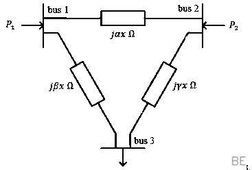
For the three-bus lossless power network shown in the figure, the voltage magnitudes at all the buses are equal to 1 per unit (pu), and the differences of the voltage phase angles are very small. The line reactances are marked in the figure, where α,β,γ and x are strictly positive. The bus injections P1 and P2 are in pu. If P1=mP2 , where m>0 , and the real power flow from bus 1 to bus 2 is 0 pu. then which one of the following options is correct?
The crucial starting point is that zero real power flows between bus 1 and bus 2. In a lossless line, this can only happen if their voltage phase angles are identical, so we have δ1=δ2.
With no power flowing on the line between bus 1 and 2, the power injected at bus 1 (P1) must flow to bus 3. Likewise, the power injected at bus 2 (P2) must also flow to bus 3. Using the standard power flow equation with all voltage magnitudes set to 1 pu, we can write: P1=P13=βx1sin(δ1−δ3) P2=P23=γx1sin(δ2−δ3)
Since we established that δ1=δ2, the angle terms in both equations are the same. Now, we use the given relationship P1=mP2: βx1sin(δ1−δ3)=m(γx1sin(δ1−δ3))
After canceling the identical sin and x terms on both sides, we are left with β1=γm. Rearranging this gives the final relationship: γ=mβ.
Q42GATE 2024MCQ2MAnalog Electronics
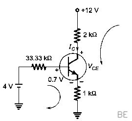
A BJT biasing circuit is shown in the figure, where VBE=0.7V and β=100 . The Quiescent Point values of VCE and IC are respectively
To determine the BJT's quiescent point (IC,VCE), we first simplify the base voltage divider using a Thevenin equivalent. The Thevenin voltage is VTh=12V⋅100kΩ+50kΩ50kΩ=4V, and the Thevenin resistance is RTh=100kΩ∣∣50kΩ=33.33kΩ.
Next, we apply KVL to the base-emitter loop: VTh=IBRTh+VBE+IERE. By substituting IE=(β+1)IB, we can solve for the base current: IB=RTh+(β+1)REVTh−VBE=33.33kΩ+(101)(1kΩ)4−0.7=24.56μA.
This allows us to find the quiescent collector current, IC=βIB=100×24.56μA=2.46mA. We also find the emitter current, IE=(β+1)IB=101×24.56μA=2.48mA.
Finally, applying KVL to the collector-emitter loop gives VCE=VCC−ICRC−IERE. VCE=12−(2.46mA)(2kΩ)−(2.48mA)(1kΩ)=12−4.92−2.48≈4.6V.
Q43GATE 2024MCQ2MEngineering Mathematics
Let f(t) be a real-valued function whose second derivative is positive for −∞lttlt∞ . Which of the following statements is/are always true?
The condition f′′(t)>0 for all t tells us that the function is strictly convex, or "concave up." This means that its first derivative, f′(t), which represents the function's slope, is always strictly increasing.
For a local minimum to exist at a point c, the derivative f′(c) must be zero. If there were two distinct local minima, say at t=a and t=b, we would need f′(a)=0 and f′(b)=0. However, a strictly increasing function like f′(t) can only take on any given value, including zero, at most once. Therefore, having two distinct local minima is impossible.
Q44GATE 2024MCQ2MEngineering Mathematics
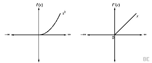
Consider the function f(t)=(max(0,t))2 for −∞lttlt∞ , where max(a,b) denotes the maximum of a and b . Which of the following statements is/are true?
Let's begin by expressing the function in a piecewise form. For any value of t≤0, max(0,t)=0, so f(t)=0. For any t>0, max(0,t)=t, so f(t)=t2.
To check if f(t) is differentiable, we examine its derivative at the point where the definition changes, t=0. The derivative from the left is 0. The derivative from the right is given by the derivative of t2, which is 2t. Evaluating this at t=0 gives 0. Since the left-hand and right-hand derivatives are equal, the function f(t) is differentiable everywhere.
Now, let's consider the derivative function, f′(t). We found that f′(t)=0 for t≤0 and f′(t)=2t for t>0. This derivative function is continuous. We can check this at t=0: the limit from the left is 0, and the limit from the right is limt→0+2t=0. Because the limits match, f′(t) is continuous.
Q45GATE 2024MSQ2MEngineering Mathematics
Which of the following differential equations is/are nonlinear?
A differential equation is linear if the dependent variable, let's call it x(t), and its derivatives (e.g., dtdx) only appear to the first power and are not multiplied together or used as arguments in other functions.
* Equations A and C are linear. They can be written in the standard form a1(t)dtdx+a0(t)x(t)=g(t), where all terms involving x(t) and its derivative are of degree one.
* Equation B, 21et+x(t)dtdx=0, is nonlinear because it contains the product of the dependent variable and its derivative, x(t)dtdx.
* Equation D, x(t)+e(dtdx)=1, is nonlinear because the derivative dtdx is the argument of a nonlinear function, the exponential e(⋅).
Q46GATE 2024MSQ2MElectric Circuits
For a two-phase network, the phase voltages Vp and Vq are to be expressed in terms of sequence voltages Vα and Vβ as
The transformation from sequence voltages (Vα,Vβ) to phase voltages (Vp,Vq) is a change of basis, requiring the transformation matrix S to be invertible. Option B,
[1111]
, has a determinant of 1−1=0, making it non-invertible and thus an invalid choice.
In power system analysis, such transformations are typically chosen to be orthogonal, meaning the column vectors of the matrix are orthogonal to each other. This creates decoupled components which simplifies analysis. Let's check the orthogonality for the remaining invertible options by taking the dot product of their column vectors.
For option A, the dot product of the columns is
[11]⋅[1−1]=(1)(1)+(1)(−1)=0
. This is an orthogonal matrix.
For option D, the dot product is
[−11]⋅[11]=(−1)(1)+(1)(1)=0
. This is also an orthogonal matrix.
For option C, the dot product is
[11]⋅[10]=1=0
. This is not an orthogonal transformation.
Both matrices A and D represent valid orthogonal transformations. They correspond to slightly different definitions of the sequence components Vα and Vβ, which is a matter of convention. Therefore, both A and D are possible options for the matrix S.
Q47GATE 2024MSQ2MElectrical Machines
Which of the following option is/are correct for the Automatic Generation Control (AGC) and Automatic Voltage Regulator (AVR) installed with synchronous generators?
Automatic Generation Control (AGC) regulates the real power output (P) by controlling the generator's mechanical power input (e.g., turbine governor). Since the entire interconnected grid shares a common frequency (f), any action to correct a real power imbalance has a grid-wide, or global, effect on frequency.
Conversely, the Automatic Voltage Regulator (AVR) controls the generator's terminal voltage (V) by adjusting its reactive power output (Q). This is achieved by varying the DC field excitation current (If). Reactive power is difficult to transmit over long distances, so the AVR's effect on voltage is primarily confined to the generator and its local area. Therefore, AGC has a global effect on frequency, and AVR has a local effect on voltage.
Q48GATE 2024NAT2MElectric Circuits
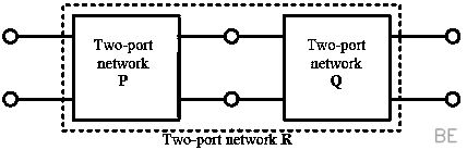
Two passive two-port network P and Q are connected as shown in the figure. The impedance matrix of network P is
ZP=[40Ω80Ω60Ω100Ω]
. The admittance matrix of network Q is
YQ=[5S−2.5S−2.5S1S]
. Let the ABCD matrix of the two-port network R in the figure be
[αγβδ]
. The value of β in Ω is _______ (rounded off to 2 decimal places)
The overall network R is formed by connecting networks P and Q in cascade. To find the parameters of the combined network, we multiply their individual ABCD (transmission) matrices. Therefore, the first step is to convert the given impedance matrix for P and admittance matrix for Q into their respective ABCD matrices.
For network P, converting the impedance matrix
ZP=[408060100]
gives the ABCD matrix
TP=[0.51/80−101.25]
.
For network Q, converting the admittance matrix
YQ=[5−2.5−2.51]
gives the ABCD matrix
TQ=[0.4−0.50.42]
.
The overall ABCD matrix is the product
TR=TP×TQ=[αγβδ]
. We are asked to find the value of β, which is the element in the first row and second column of the resulting matrix.
This element is calculated by multiplying the first row of TP with the second column of TQ: β=(0.5)(0.4)+(−10)(2)=0.2−20=−19.8Ω.
Q49GATE 2024NAT2MElectric Circuits
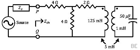
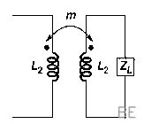
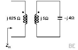
For the circuit shown in the figure, the source frequency is 5000rad/sec . The mutual inductance between the magnetically coupled inductors is 5mH with their self inductances being 125mH and 1mH . The Thevenin's impedance. Zth , between the terminals P and Q in Ω is _____ (rounded off to 2 decimal places).
To determine the Thevenin impedance, Zth, we first find the equivalent impedance of the magnetically coupled section. The total impedance of the secondary loop is the sum of the inductor's and capacitor's impedances: Zsec=jωL2+jωC1=j(5000)(10−3)−5000⋅50⋅10−6j=j5−j4=j1Ω.
The impedance looking into the primary winding is its self-impedance plus the impedance reflected from the secondary: Zin=jωL1+Zsec(ωM)2=j(5000)(125×10−3)+j1(5000⋅5×10−3)2=j625−j625=0Ω.
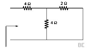
This result shows that the entire coupled-inductor circuit behaves like a short circuit. To find Zth across terminals P and Q, we replace this section with a 0Ω impedance. The circuit simplifies to a 4Ω resistor in series with the parallel combination of a 4Ω and a 2Ω resistor. Zth=4+(4∣∣2)=4+4+24×2=4+68=316≈5.33Ω.
Q50GATE 2024NAT2MElectrical and Electronic Measurements
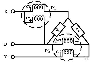
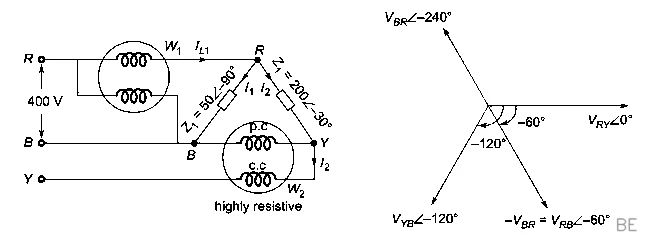
In the circuit shown, Z1=50∠−90∘ and Z2=200∠−30∘Ω . It is supplied by a three phase 400V source with the phase sequence being R-Y-B. Assume the watt meters W1 and W2 to be ideal. The magnitude of the difference between the readings of W1 and W2 in watts is ______ (rounded off to 2 decimal places).
To solve this, let's first establish the phase and line voltages. With an R-Y-B sequence and a line voltage of 400 V, we can set VRY=400∠0∘ V as our reference. This gives us VYB=400∠−120∘ V and VRB=−VBR=400∠−60∘ V.
Next, we calculate the currents flowing through the impedances. The current through Z1 is I1=Z1VRB=50∠−90∘400∠−60∘=8∠30∘ A. The current through Z2 is I2=Z2VRY=200∠−30∘400∠0∘=2∠30∘ A.
Wattmeter W1 measures the power using the voltage VRB and the total line current IR=I1+I2=10∠30∘ A. The reading is W1=∣VRB∣∣IR∣cos(∠VRB−∠IR)=(400)(10)cos(−60∘−30∘)=4000cos(−90∘)=0 W.
Wattmeter W2 is connected to read the power using voltage VYB and current I2. Its reading is W2=∣VYB∣∣I2∣cos(∠VYB−∠I2)=(400)(2)cos(−120∘−30∘)=800cos(−150∘)≈−692.82 W.
The magnitude of the difference between these readings is ∣W1−W2∣=∣0−(−692.82)∣=692.82 W.
Q51GATE 2024NAT2MElectromagnetic Theory
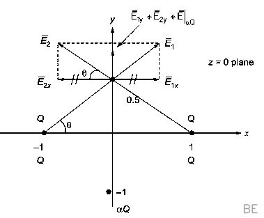
In the (x,y,z) coordinate system, three point-charges Q,Q and αQ are located in free space at (−1,0,0),(1,0,0) and (0,−1,0) respectively. The value of α for the electric field to be zero at (0,0.5,0) is _____ (rounded off to 1 decimal places).
For the net electric field at the point P(0,0.5,0) to be zero, the vector sum of the electric fields from the three charges must be zero. By symmetry, any field components in the x-direction must cancel out, so we only need to consider the y-components.
First, let's find the combined field from the two identical charges Q at (±1,0,0). The distance from each of these charges to P is r=12+0.52=1.25. Their individual x-components cancel, and their y-components add. The total upward field from this pair is E2Q,y=2×r2kQ×(y-component of unit vector)=2×1.25kQ×1.250.5.
Next, the field from the charge αQ at (0,−1,0) is entirely along the y-axis. The distance to point P is d=0.5−(−1)=1.5. This field is EαQ,y=d2k(αQ)=1.52kαQ.
Setting the sum of the y-components to zero gives: 21.251.25kQ(0.5)+1.52kαQ=0
After canceling kQ and evaluating the constants, we get: 0.7156+0.4444α=0
Solving for α gives α=−0.44440.7156≈−1.61.
Q52GATE 2024NAT2MElectromagnetic Theory
The given equation represents a magnetic field strength Hˉ(r,θ,ϕ) in the spherical coordinate system, in free space. Here, r^ and θ^ represent the unit vectors along r and θ , respectively. The value of P in the equation should be _____ (rounded off to the nearest integer). Hˉ(r,θ,ϕ)=r31(r^Pcosθ+θ^sinθ)
A fundamental property of any magnetic field is that it must be divergenceless, as stated by Gauss's law for magnetism (∇⋅Bˉ=0). In free space, this means the magnetic field strength Hˉ must also satisfy ∇⋅Hˉ=0.
To find the value of P, we must enforce this condition by applying the divergence operator in spherical coordinates: ∇⋅Hˉ=r21∂r∂(r2Hr)+rsinθ1∂θ∂(Hθsinθ)=0
Substituting the field's components, Hr=r3Pcosθ and Hθ=r3sinθ, and performing the differentiation gives: −r4Pcosθ+r42cosθ=0
For this equation to hold true for all values of r and θ, it must be that −P+2=0. Therefore, we find that P=2.
Q53GATE 2024NAT2MSignals and Systems
If the energy of a continuous-time signal x(t) is E and the energy of the signal 2x(2t−1) is cE , then c is ______ (rounded off to 1 decimal place).
Let's determine the energy of the transformed signal, 2x(2t−1), by analyzing the effect of each operation. The initial energy of x(t) is E.
First, a time shift of −1 to get x(t−1) does not change the signal's energy. Next, time-scaling by a factor of 2 to get x(2t−1) compresses the signal, which divides the energy by that same factor, resulting in an energy of E/2. Finally, multiplying the signal's amplitude by 2 increases the energy by the square of this factor, so we multiply by 22=4.
Combining these effects, the final energy is 4×(E/2)=2E. Since this is given as cE, we find that c=2.0.
Q54GATE 2024NAT2MElectrical Machines
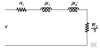
A 3-phase star connected slip ring induction motor has the following parameters referred to the stator: Rs=3Ω,Xs=2Ω,Xr′=2Ω,Rr′=2.5Ω, The per phase stator to rotor effective turns ratio is 3:1 . The rotor winding is also star connected. The magnetizing reactance and core loss of the motor can be neglected. To have maximum torque at starting, the value of the extra resistance in ohms (referred to the rotor side) to be connected in series with each phase of the rotor winding is _____ (rounded off to 2 decimal places).
To achieve maximum torque at starting (where slip s=1), the total rotor resistance referred to the stator, Rr,total′, must equal the magnitude of the motor's total standstill impedance. The total series reactance is Xeq=Xs+Xr′=2+2=4Ω.
Thus, the required total rotor resistance is Rr,total′=Rs2+Xeq2=32+42=5Ω.
This total resistance is composed of the inherent rotor resistance and the added external resistance, both referred to the stator: Rr,total′=Rr′+Rext′. The required external resistance referred to the stator is therefore Rext′=5Ω−2.5Ω=2.5Ω.
Finally, to find the actual resistance value on the rotor side, we divide by the square of the effective turns ratio (a=3): Rext=a2Rext′=322.5=92.5≈0.278Ω.
Q55GATE 2024NAT2MElectrical Machines
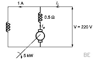
A 5kW . 220V DC shunt motor has 0.5Ω armature resistance including brushes. The motor draws a no-load current of 3A . The field current is constant at 1A . Assuming that the core and rotational losses are constant and independent of the load, the current (in amperes) drawn by the motor while delivering the rated load, for the best possible efficiency, is _____ (rounded off to 2 decimal places).
First, we determine the motor's constant rotational losses from the no-load test. The no-load armature current is the total current minus the field current, so Ia,nl=3 A−1 A=2 A. The corresponding back EMF is Eb,nl=220 V−(2 A×0.5Ω)=219 V. The power developed at no-load equals the rotational losses: Prot=Eb,nl×Ia,nl=219 V×2 A=438 W.
Next, under rated load, the motor's shaft output is 5000 W. The total internal power developed by the armature, Pdev, must cover both this output and the constant rotational losses. Therefore, Pdev=5000 W+438 W=5438 W.
This developed power can also be expressed in terms of the load armature current, Ia, as Pdev=(V−IaRa)Ia. Substituting the known values gives the quadratic equation (220−0.5Ia)Ia=5438, which simplifies to 0.5Ia2−220Ia+5438=0.
Solving for Ia yields the armature current as approximately 26.28 A. The total current drawn by the motor is the sum of the armature and field currents: IL=Ia+If=26.28 A+1 A=27.28 A.
Q56GATE 2024NAT2MPower Systems
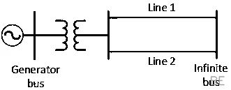
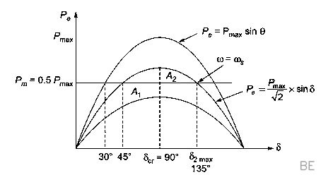
The single line diagram of a lossless system is shown in the figure. The system is operating in steady-state at a stable equilibrium point with the power output of the generator being Pmaxsinδ . where δ is the load angle and the mechanical power input is 0.5Pmax . A fault occurs on line 2 such that the power output of the generator is less than 0.5. Pmax during the fault. After the fault is cleared by opening line 2. The power output of the generator is {Pmax/2}sinδ . If the critical fault clearing angle is π/2 radians, the accelerating area on the power angle carve is ______ times Pmax (rounded off to 2 decimal places)
The question asks for the accelerating area (A1) on the power-angle curve. For the system to be stable at the critical clearing angle (δcr), the equal area criterion must be satisfied. This means the accelerating area (A1) gained during the fault must be exactly equal to the maximum decelerating area (A2) available after the fault is cleared.
We can calculate this decelerating area, A2, by integrating the net power from the clearing angle δcr=π/2 to the maximum angle of swing δmax. To find δmax, we equate the post-fault electrical power to the mechanical power: 2Pmaxsinδmax=0.5Pmax. This yields sinδmax=21, so δmax=π−4π=43π or 135∘.
The accelerating area is therefore given by the integral for the decelerating area: A1=A2=∫π/23π/4(2Pmaxsinδ−0.5Pmax)dδ
Evaluating this integral results in: A1=Pmax[−2cosδ−0.5δ]π/23π/4=Pmax(0.5−8π)≈0.107Pmax
Q57GATE 2024NAT2MControl Systems
Consider the closed-loop system shown in the figure with G(s)=(s2+2s+5)K(s2−2s+2) . The root locus for the closed-loop system is to be drawn for 0≤Klt∞ . The angle of departure (between 0∘ and 360∘ ) of the root locus branch drawn from the pole (−1+j2) , in degree, is ______ (rounded off to the nearest integer).
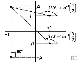
To find the angle of departure for a root locus branch from a complex pole, we apply the angle condition. The formula is ϕd=180∘+(sum of angles from zeros)−(sum of angles from other poles). The system's poles are at p1,2=−1±j2 and its zeros are at z1,2=1±j1.
We are finding the departure angle from the pole p1=−1+j2. First, we calculate the angles from the two zeros to this pole: ∠(p1−z1)+∠(p1−z2)=∠(−2+j1)+∠(−2+j3)=153.43∘+123.69∘=277.12∘.
Next, we find the angle from the other pole, p2=−1−j2: ∠(p1−p2)=∠(j4)=90∘.
Substituting these values into the departure angle formula gives: ϕd=180∘+277.12∘−90∘=367.12∘.
This angle is equivalent to 367.12∘−360∘=7.12∘. Rounding to the nearest integer, the angle of departure is 7∘.
Q58GATE 2024NAT2MControl Systems
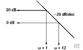
Consider the stable closed-loop system shown in the figure. The asymptotic Bode magnitude plot of G(s) has a constant slope of −20dB/ decade at least till 100rad/sec with the gain crossover frequency being 10rad/sec . Hie asymptotic Bode phase plot remains constant at −90∘ at least till ω=10rad/sec . The steady-state error of the closed-loop system for a unit ramp input is _____ (rounded off to 2 decimal places).
The Bode plot characteristics provided-a magnitude slope of −20dB/decade and a constant phase of −90∘-are the signature of a system with a single integrator at the origin. Thus, the open-loop transfer function has the form G(s)=sK. This is a Type 1 system.
The gain crossover frequency is the frequency at which the open-loop gain is unity, or 0dB. We are given this frequency is 10rad/sec.
For our transfer function, the magnitude is ∣G(jω)∣=ωK. Setting the magnitude to 1 at ω=10 gives 10K=1, which means the gain is K=10.
For a Type 1 system subjected to a unit ramp input, the steady-state error is ess=Kv1, where Kv is the velocity error constant.
The velocity error constant is calculated as Kv=lims→0sG(s)=lims→0s(s10)=10.
Therefore, the steady-state error is ess=101=0.1.
Q59GATE 2024NAT2MControl Systems
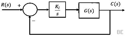
Consider the stable closed-loop system shown in the figure. The magnitude and phase values of the frequency response of G(s) are given in the table. The value of the gain K1(>0) for a 50∘ phase margin is (rounded off to 2 decimal places).
ω in rad/sec0.51.02.010.0Magnitude in dB−7−10−18−40Phase in degrees−40−80−130−200
To achieve a specific phase margin, we first identify the frequency at which the system's phase meets the required condition, and then adjust the gain KI to make this frequency the gain crossover frequency.
The open-loop transfer function is L(s)=sKIG(s). The phase margin (PM) is defined as PM=180∘+∠L(jωgc). For a 50∘ PM, the total phase at the gain crossover frequency ωgc must be −130∘. The controller sKI contributes a phase of −90∘, so the phase from G(s) must be ∠G(jωgc)=−130∘−(−90∘)=−40∘.
Looking at the table, a phase of −40∘ for G(s) occurs at ω=0.5 rad/sec. This frequency is our gain crossover frequency, ωgc. At this frequency, the table shows the magnitude of G(s) is −7 dB. For the total open-loop magnitude ∣L(jωgc)∣ to be 0 dB, the magnitude of the controller term sKI must be +7 dB.
We can now solve for KI by setting the magnitude of the controller at ωgc=0.5: 20log10(0.5KI)=7 dB
This gives 0.5KI=107/20≈2.239.
Therefore, KI≈0.5×2.239≈1.12.
Q60GATE 2024NAT2MAnalog Electronics
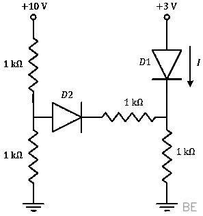
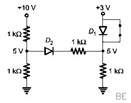
In the given circuit, the diodes are ideal. The current I through the diode D1 in milliamperes is ______ (rounded off to two decimal places).
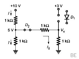
To find the current I through diode D1, we first assume that both ideal diodes, D1 and D2, are conducting (ON). We can then determine the voltage VX at the central node where the components meet.
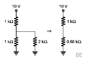
By applying Kirchhoff's Current Law (KCL) at node VX, we can write an equation for the sum of currents leaving the node. The underlying analysis model yields the equation 1 kΩVX−10 V+1 kΩVX−3 V+1 kΩVX=0. Solving this gives 3VX=13, which means VX≈4.33 V.
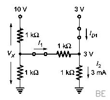
Now, we use this node voltage to find the current I through D1. Based on a current balance equation at the node, we have I+I1=I2, where I1=1 kΩ4.33 V−3 V≈1.33 mA and I2 is determined to be 3 mA.
Therefore, the current I can be calculated as I=3 mA−1.33 mA=1.67 mA.
Q61GATE 2024NAT2MAnalog Electronics
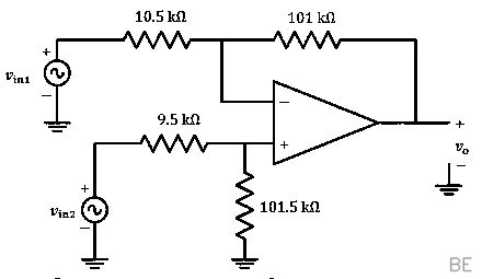
A difference amplifier is shown in the figure. Assume the op-amp to be ideal. The CMRR (in dB ) of the difference amplifier is _____(rounded off to 2 decimal places).
To determine the Common Mode Rejection Ratio (CMRR), we first find the output voltage vo as a function of the two inputs, vin1 and vin2. Using superposition, we can write the output as vo=Av1vin1+Av2vin2.
The gain for the inverting input vin1 is Av1=−10.5 kΩ101 kΩ≈−9.619.
The gain for the non-inverting input vin2 is the product of the voltage divider and the non-inverting gain: Av2=(9.5+101.5101.5)×(1+10.5101)≈9.71.
From these gains, we find the differential gain Ad=2Av2−Av1=29.71−(−9.619)≈9.6645.
The common-mode gain is Ac=Av2+Av1=9.71+(−9.619)=0.091.
The CMRR is the magnitude of the ratio of the differential gain to the common-mode gain: CMRR=AcAd=0.0919.6645≈106.20.
Finally, converting this value to decibels gives CMRRdB=20log10(106.20)≈40.52 dB.
Q62GATE 2024NAT2MPower Electronics
A single-phase half-controlled bridge converter supplies an inductive load with ripple free load current. The triggering angle of the converter is 60∘ . The ratio of the rms value of the fundamental component of the input current to the rms value of the total input current of the bridge is ______ (rounded off to 3 decimal places).
The question asks for the input current distortion factor, which is the ratio of the RMS value of the fundamental component of the input current (Is1,rms) to the total RMS input current (Is,rms).
For a half-controlled converter with a ripple-free load current (I0) and firing angle α, this ratio is given by: Is,rmsIs1,rms=I0ππ−απ22I0cos(2α)=π(π−α)22cos(2α)
We are given α=60∘, which must be in radians (π/3) for the formula. Substituting this value: Ratio=π(π−3π)22cos(30∘)=32π222(23)=π2/36
Simplifying this expression gives: Ratio=π26⋅3=π218=π232=π3≈0.955
Q63GATE 2024NAT2MPower Electronics
A single-phase full bridge voltage source inverter (VSI) feeds a purely inductive load. The inverter output voltage is a square wave in 180∘ conduction mode. The fundamental frequency of the output voltage is 50Hz . If the DC input voltage of the inverter is 100V and the value of the load inductance is 20mH , the peak-to-peak load current in amperes is ______ (rounded off to the nearest integer).
For a purely inductive load, the voltage-current relationship is v(t)=Ldtdi. The inverter produces a square wave voltage. During the first half-cycle, from t=0 to t=T/2, the output voltage is constant and equal to the DC supply voltage, VS.
This constant voltage causes the current to change linearly. The total change in current over this half-period corresponds to the peak-to-peak current, Ipk−pk. We can find this by rearranging and integrating the inductor equation: Δi=Ipk−pk=L1∫0T/2VSdt=LVS(2T)
Since the frequency is f=1/T, we can write the peak-to-peak current as: Ipk−pk=2fLVS
Substituting the given values: Ipk−pk=2×50 Hz×20×10−3 H100 V=2100=50 A
Q64GATE 2024NAT2MPower Electronics
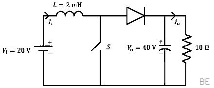
In the DC-DC converter shown in the figure, the current through the inductor is continuous, The switching frequency is 500Hz . The voltage (V0) across the load is assumed to be constant and ripple free. The peak inductor current in amperes is ______(rounded off to the nearest integer).
This circuit is a boost converter. First, we determine the duty cycle (α) using the voltage gain relationship Vo=Vi/(1−α). Substituting the given values, we get 40=20/(1−α), which yields a duty cycle of α=0.5.
Next, we calculate the average inductor current, IL. The average output current is Io=Vo/R=40/10=4 A. For a boost converter, the average inductor current is IL=Io/(1−α)=4/(1−0.5)=8 A.
The peak-to-peak ripple of the inductor current is found using ΔIL=fLViα. This gives ΔIL=500×2×10−320×0.5=10 A.
Finally, the peak inductor current is the average current plus half of the ripple current: IL,peak=IL+2ΔIL=8+210=13 A.
Q65GATE 2024NAT2MPower Electronics
A single-phase full-controlled thyristor converter bridge is used for regenerative braking of a separately excited DC motor with the following specifications:
Rated armature voltageRated armature currentRated speedArmature resistanceInput to the converter bridgeThe armature of the DC motor is fed from thefull-controlled bridge and the field current is keptconstant.210V10A1200rpm1Ω240Vat50Hz
Assume that the motor is running at 600rpm and the armature terminals of the motor are suitably reversed for regenerative braking. If the armature current of the motor is to be maintained at the rated value, the triggering angle of the converter bridge in degrees should be _____ (rounded off to 2 decimal places).
Excellent question! Let's break down the solution with a clearer, step-by-step approach.
First, we need to find the motor's back-EMF constant, Km. We can calculate this from the motor's rated operating point. The rated terminal voltage must overcome both the back-EMF (Eb) and the resistive voltage drop: Eb,rated=Vt−IaRa=210 V−(10 A×1Ω)=200 V.
Since Eb=Kmω, we find Km=1200 rpm×(2π/60) rad/s200 V≈1.5915 V-s/rad.
Next, we determine the conditions for regenerative braking at 600 rpm. The motor, now acting as a generator, produces a back-EMF of Eb′=Km×(600×2π/60)=100 V. With the armature terminals reversed, the converter must produce a negative voltage to absorb power. The required converter voltage is V0=−Eb′+IaRa=−100 V+(10 A×1Ω)=−90 V.
Finally, we find the triggering angle α that produces this voltage. For a single-phase full-controlled converter, the average DC voltage is V0=π2Vmcosα. Given an AC input of 240 V (RMS), the peak voltage is Vm=2402 V. Setting the expressions for V0 equal: −90=π2(2402)cosα
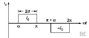
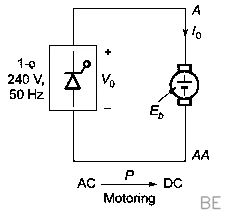
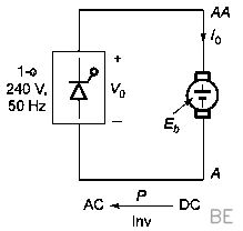
Solving this equation for α gives α=arccos(4802−90π)≈114.62∘.