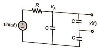
Q21GATE 2014MCQ
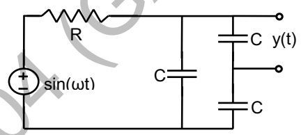
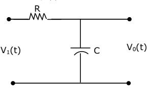
The steady state output of the circuit shown in the figure is given by . If the amplitude = 0.25, then the frequency is
GATE ECE · Network Theory
Generate GATE-level questions on Sinusoidal Steady State Analysis. Focus on: 1. Phasors and complex impedance. 2. Resonance in series and parallel RLC circuits. 3. Power calculations: real, reactive and complex power.
37 questions · 17 PYQs · 0 AI practice · GATE ECE 2027
The steady state output of the circuit shown in the figure is given by . If the amplitude = 0.25, then the frequency is
Two magnetically uncoupled inductive coils have Q factors and at the chosen operating frequency. Their respective resistances are and When connected in series, their effective Q factor at the same operating frequency is
The circuit shown below is driven by a sinusoidal input . The steady state output
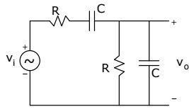
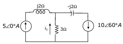
The current I in the circuit shown is
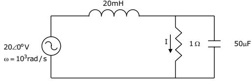
For parallel RLC circuit, which one of the following statements is NOT correct?
An AC source of RMS voltage 20 V with internal impedance feeds a load of impedance in the figure below. The reactive power consumed by the load is

In the ac network shown in the figure, the phasor voltage (in Volts) is
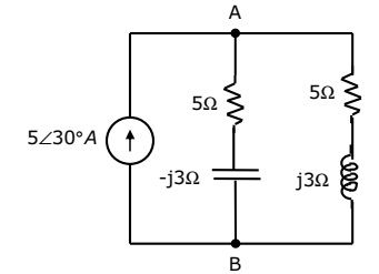
The condition on R, L and C such that the step response y(t) in the figure has no oscillations, is
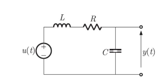
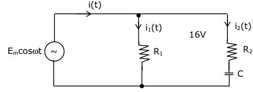
For the circuit shown in the figure, the instantaneous current (t) is
In a series RLC circuit, R=2k , L=1H, and The resonant frequency is
Consider the following statements S1 and S2 S1 : At the resonant frequency the impedance of a series RLC circuit is zero. S2 : In a parallel GLC circuit, increasing the conductance G results in increase in its Q factor. Which one of the following is correct?
The circuit shown in the figure, with and C = 3 F has input voltage v(t) = sin2t. The resulting current i(t) is
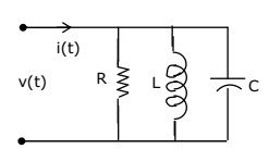
The transfer function of an RLC circuit is given by . The Quality factor (Q-factor) of this circuit is
For the circuit shown in the figure, the time constant RC = 1 ms. The input voltage is . The output voltage is equal to
An input voltage is applied to a series combination of resistance R = 1 and an inductance L = 1 H. The resulting steady-state current i(t) in ampere is
A series RLC circuit has a resonance frequency of 1 kHz and a quality factor Q=100. If each of R, L and C is doubled from its original value, the new Q of the circuit is
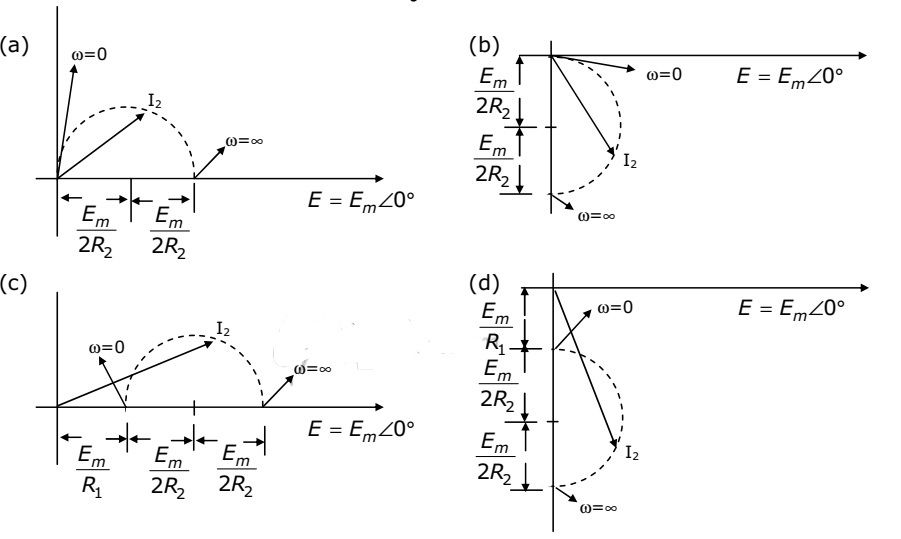
When the angular frequency in figure is varied from 0 to , the locus of the current phasor is given by
Want unlimited AI-generated Sinusoidal Steady State questions?
Sign up free and practice with adaptive difficulty — Easy, Medium, Hard. New questions every session.
Start practising for free →