Q1GATE 2025MCQ
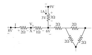
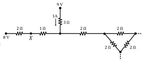
Consider a part of an electrical network as shown below. Some node voltages, and the current flowing through the resistor are as indicated. The voltage (in Volts) at node X is __________ .
GATE ECE · Network Theory
Generate GATE-level questions on Basics of Network Analysis. Focus on: 1. Network solution methods: nodal and mesh analysis. 2. Transient response of dc and ac networks. 3. Basic laws: Ohm's law, KCL, KVL.
50 questions · 20 PYQs · 0 AI practice · GATE ECE 2027
🎯 These are sample questions
Just sign in to unlock everything. Free for all students.
Consider a part of an electrical network as shown below. Some node voltages, and the current flowing through the resistor are as indicated. The voltage (in Volts) at node X is __________ .
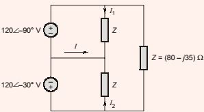
Let , and be the currents flowing through the capacitor, inductor, and resistor, respectively, in the circuit given below. The AC admittances are given in Siemens (S). Which one of the following is TRUE?

In the given circuit, the current (in ) is _____
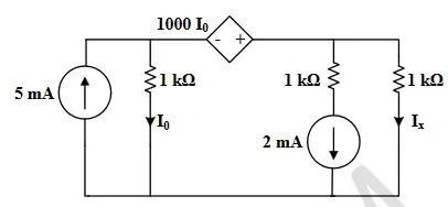
In the circuit shown below, the current flowing through resistor is ____ (rounded off to two decimal places).
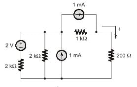
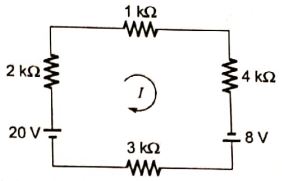
The current in the circuit shown is ________
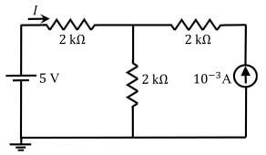
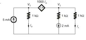
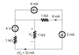
Consider the circuit shown in the figure. The current flowing through the resistor is _________.
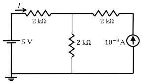
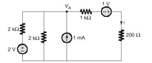
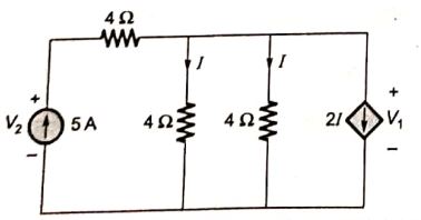
Consider the circuit shown in the figure. The value of (rounded off to one decimal place) is _________ V.
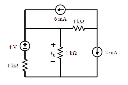
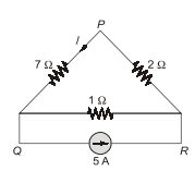
Consider the circuit shown in the figure. The current I flowing through the resistor between P and Q (rounded off to one decimal place) is ________ A.
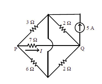
The current I in the given network is
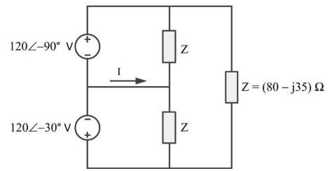
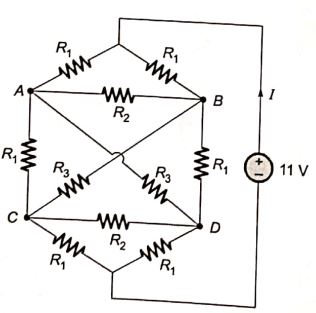
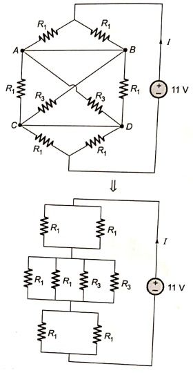
Consider the network shown below with . The network is connected to a constant voltage source of 11V. The magnitude of the current (in amperes, accurate to two decimal places) through the source is _______.
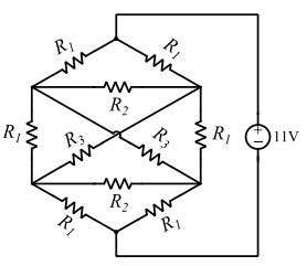
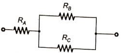
A connection is made consisting of resistance A in series with a parallel combination of resistances B and C. Three resistors of value 10 , 5 , 2 are provided. Consider all possible permutations of the given resistors into the positions A, B, C, and identify the configurations with maximum possible overall resistance, and also the ones with minimum possible overall resistance. The ratio of maximum to minimum values of the resistances (up to second decimal place) is ____________.
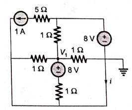
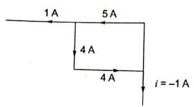
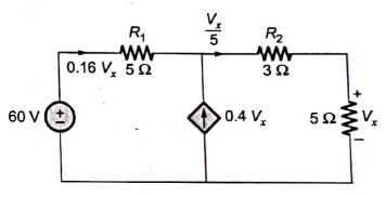
In the figure shown, the current i (in ampere) is __________
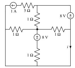
In the circuit shown in the figure, the magnitude of the current (in amperes) through is ___
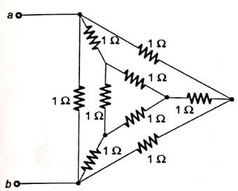
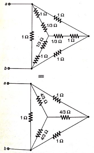
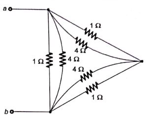
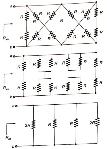
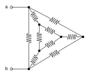
In the given circuit, each resistor has a value equal to 1 . What is the equivalent resistance across the terminals a and b?
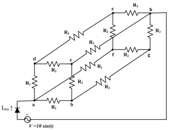
An AC voltage source V = 10 sin(t) volts is applied to the following network. Assume that , and , and that the diode is ideal. RMS current (in mA) through the diode is ________
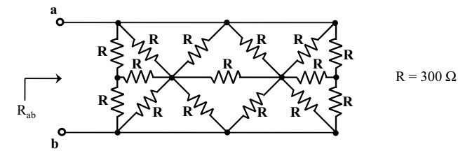
In the network shown in the figure, all resistors are identical with R = 300 . The resistance (in ) of the network is ______.
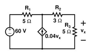
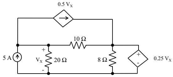
In the circuit shown, the voltage (in Volts) is _______.
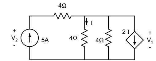
In the given circuit, the values of respectively are
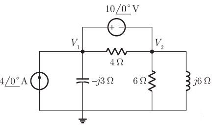
In the circuit shown in the figure, the value of node voltage is
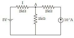
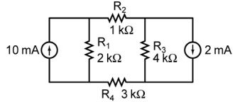
The magnitude of current (in mA) through the resistor in the figure shown is______.
Want unlimited AI-generated Basics Of Network Analysis questions?
Sign up free and practice with adaptive difficulty — Easy, Medium, Hard. New questions every session.
Start practising for free →