Q21GATE 2014MCQ
For a parallel plate transmission line, let v be the speed of propagation and Z be the characteristic impedance. Neglecting fringe effects, a reduction of the spacing between the plates by a factor of two results in
GATE ECE · Electromagnetics
Generate GATE-level questions on Transmission Lines. Focus on: 1. Characterstic impedance, Propagation constant, and Reflection coefficient. 2. Standing Wave Ratio (SWR) and Impedance transformation. 3. Smith Chart: Usage for impedance calculation and matching. 4. Impedance matching: Quarter-wave transformers and Stub matching.
48 questions · 20 PYQs · 0 AI practice · GATE ECE 2027
For a parallel plate transmission line, let v be the speed of propagation and Z be the characteristic impedance. Neglecting fringe effects, a reduction of the spacing between the plates by a factor of two results in
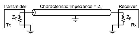
In the following figure, the transmitter sends a wideband modulated RF signal via a coaxial cable to the receiver . The output impedance of , the characteristic impedance of the cable and the input impedance of are all real.
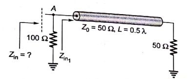
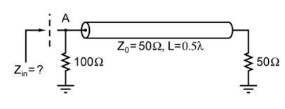
In the transmission line shown, the impedance (in ohms) between node A and the ground is _____.
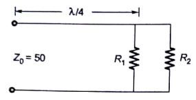
The input impedance of a section of a lossless transmission line of characteristic impedance 50 is found to be real when the other end is terminated by a load . If X is 30 , the value of R(in ) is_____.
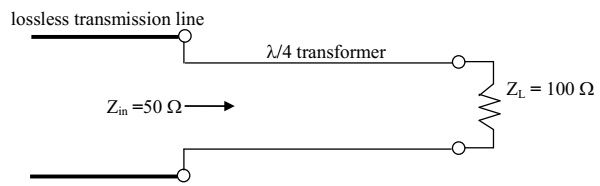
To maximize power transfer, a lossless transmission line is to be matched to a resistive load impedance via a transformer as shown. The characteristic impedance (in ) of the transformer is ___
The return loss of a device is found to be 20 dB. The voltage standing wave ratio (VSWR) and magnitude of reflection coefficient are respectively
A coaxial cable with an inner diameter of 1 mm and outer diameter of 2.4 mm is filled with a dielectric of relative permittivity 10.89. Given , the characteristic impedance of the cable is
A transmission line with a characteristic impedance of 100 is used to match a 50 section to a 200 section. If the matching is to be done both at 429 MHz and 1 GHz, the length of the transmission line can be approximately
A transmission line of characteristic impedance 50 W is terminated by a 50 load. When excited by a sinusoidal voltage source at 10 GHz, the phase difference between two points spaced 2 mm apart on the line is found to radians. The phase velocity of the wave along the line is
A transmission line of characteristic impedance 50 is terminated in a load impedance . The VSWR of the line is measured as 5 and the first of the voltage maxima in the line is observed at a distance of from the load. The value of is
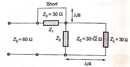
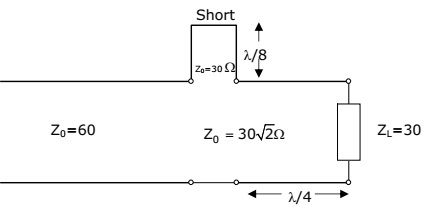
In the circuit shown, all the transmission line sections are lossless. The Voltage Standing Wave Ration(VSWR) on the 60 line is
A transmission line has a characteristic impedance of 50 and a resistance of 0.1 /m . If the line is distortion less, the attenuation constant(in Np/m) is
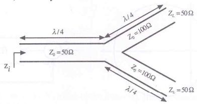
A transmission line terminates in two branches, each of length , as shown. The branches are terminated by 50 loads. The lines are lossless and have the characteristic impedances shown. Determine the impedance as seen by the source
One end of a loss-less transmission line having the characteristic impedance of 75 and length of 1 cm is short-circuited. At 3 GHz, the input impedance at the other end of transmission line is
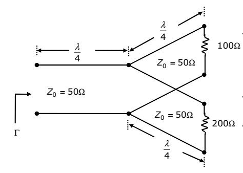
The parallel branches of a 2-wire transmission line re terminated in 100 and 200 resistors as shown in the figure. The characteristic impedance of the line is and each section has a length of . The voltage reflection coefficient at the input is
A 30-Volts battery with zero source resistance is connected to a coaxial line of characteristic impedance of 50 Ohms at t=0 second terminated in an unknown resistive load. The line length is that it takes 400 s for an electromagnetic wave to travel from source end to load end and vice-versa. At t=400 s, the voltage at the load end is found to be 40 Volts. The steady-state current through the load resistance is
Voltage standing wave pattern in a lossless transmission line with characteristic impedance 50 and a resistive load is shown in figure. The reflection coefficient is given by

Characteristic impedance of a transmission line is 50 . Input impedance of the open-circuited line . when the transmission line a short circuited, then value of the input impedance will be.
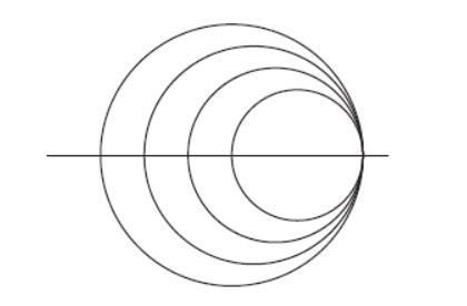
Many circles are drawn in a Smith Chart used for transmission line calculations. The circles shown in the figure represent
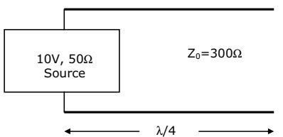
Consider a 300 , quarter-wave long (at 1 GHz) transmission line as shown in Fig. It is connected to a 10V, 50 source at one end and is left open circuited at the other end. The magnitude of the voltage at the open circuit end of the line is
Want unlimited AI-generated Transmission Lines questions?
Sign up free and practice with adaptive difficulty — Easy, Medium, Hard. New questions every session.
Start practising for free →